GB
20027974
11
AIR GATE ADJUSTMENT
To regulate the combustion air, adjust the manual air gate (3), by
loosening the locking screws (4).
Once the optimal adjustment is reached, tighten the locking
screws (4).
EXAMPLE SETTING - (for natural gas)
To set the air intake for a desired burner output of 450,000 Btu/hr,
use TABLE to determine the correct air gate setting.
In this case, the setting would be 1.8 for natural gas.
Turn the manual air gate (3) until the arrow points to 1.8 on the
scale.
Tighten locking screws (4).
All settings in TABLE are obtained with zero (0) pressure in the
combustion zone and at normal operating temperatures. i.e.,
steady state hot conditions.
Note: Burner must be fired ONLY
with fuel that is listed on the burner serial label.
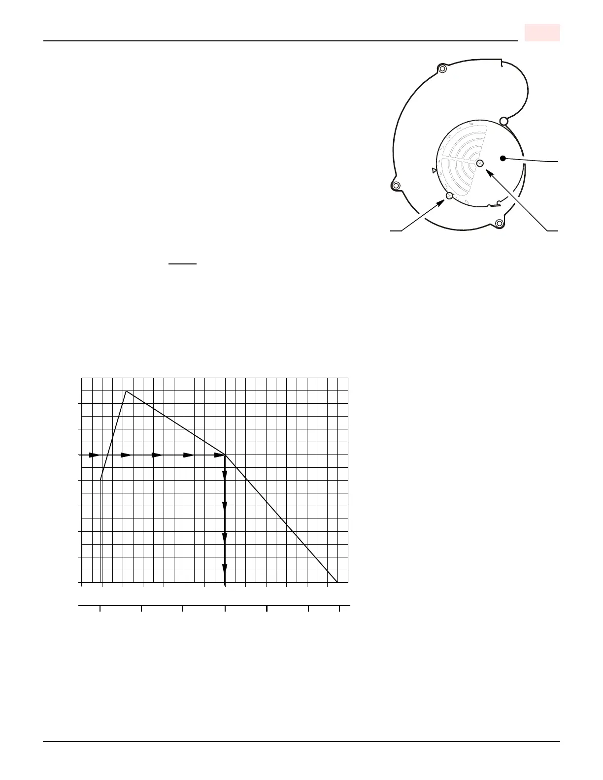
PRESSURE WORKING CHART
The chart below shows effects of pressure in the combustion zone on the minimum/maximum burner outputs.
In this example, with a maximum operating pressure of 1.0 inches water column in the combustion zone, you will
be able to obtain a maximum of 615 KBtu/h burner output.
Any change from zero (0) pressure in the combustion zone will affect the KBtu output of the burner. To supply the
required input to the appliance, manifold pressure will have to be adjusted to compensate for this condition.
PRESSURE WORKING CHART
Natural and Propane Gas
Pressure - In/wc
0.8
0.4
1.2
1.4
MBtu/h
kW/h
0.0
60
205
1.6
1.0
0.6
0.2
220
260
180100 14040
311 472 615 751 888
D10659
900
265
 Loading...