31
20154244
Maintenance
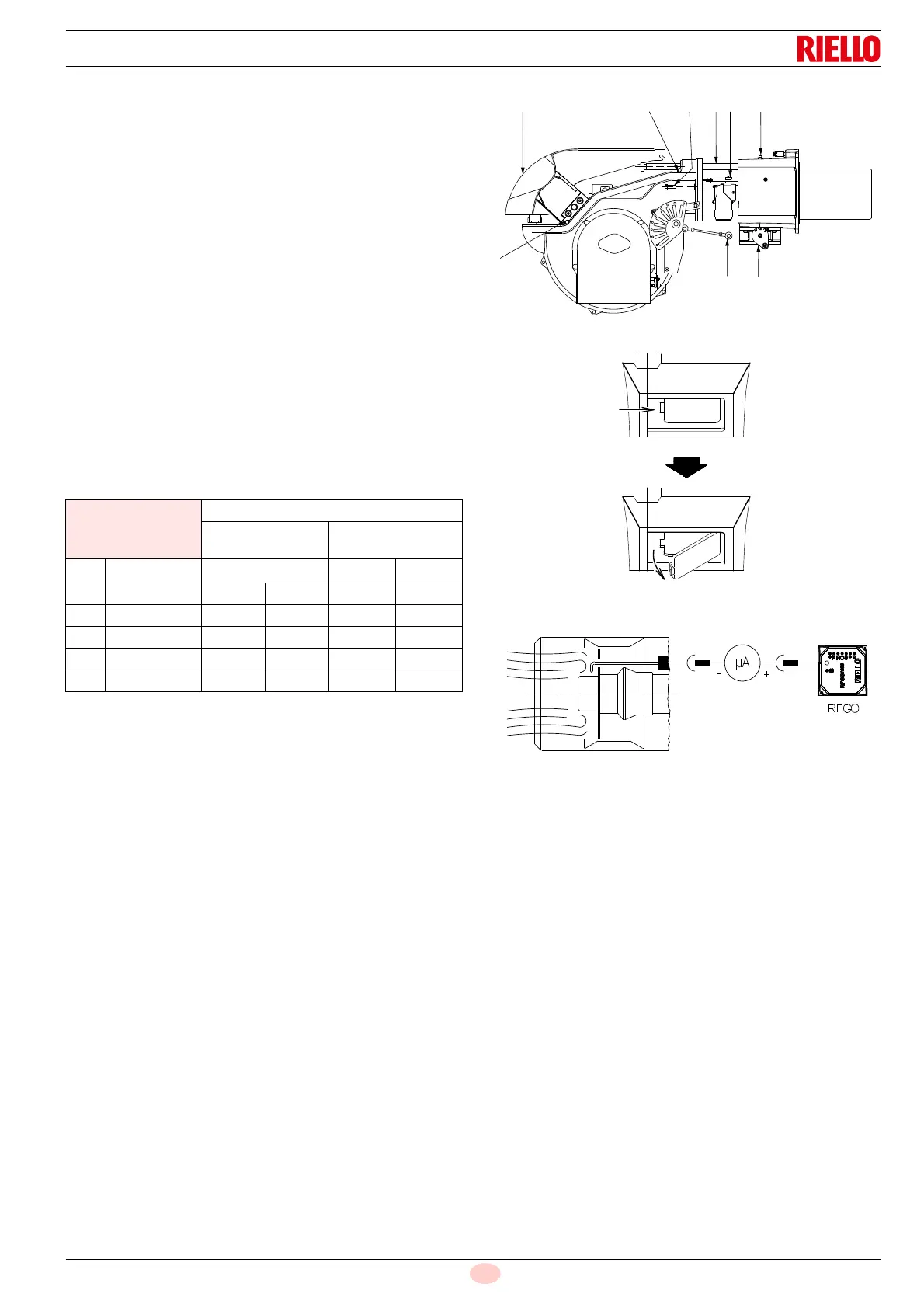
Combustion head
Open the burner and make sure that all components of the
combustion head are in good condition, not deformed by the
high temperatures, free of impurities from the surroundings
and correctly positioned. If in doubt, disassemble the elbow
5)(Fig. 37).
Gas filter
Change the gas filter when it is dirty.
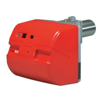
Flame inspection window
Clean the glass of the flame inspection window (Fig. 38).
Combustion
Carry out an analysis of the combustion flue gases.
Significant differences with respect to the previous
measurements indicate the points where most care should be
exercised during maintenance.
If the combustion values measured before starting maintenance
do not comply with applicable Standards or do not indicate
efficient combustion, consult the Tab. J or contact our Technical
Support Service to implement the necessary adjustments.
It is advisable to set the burner according to the type of gas used
and following the indications in Tab. J.
Tab. J
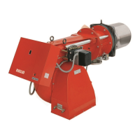
7.2.4 Flame presence check
The burner is fitted with an ionisation system to check that a
flame is present.
The minimum current for control box operation is 6 µA.
The burner provides a much higher current, so that no check is
usually needed.
However, if it is necessary to measure the ionisation current,
disconnect the plug-socket 1)(Fig. 5 on page 12) on the
ionisation probe cable and insert a full scale 100 µA direct current
microammeter. Carefully check the polarities!
The quantity of flame signal can also be checked through the
"Check Mode" function.
Check the level of the flame detection signal with the “Check
mode” function from the flame control: LEDS from 2 to 6 indicate
the flame signal level, respectively.
See “LED indicator and special function” page 33.
Check Mode
With burner flame on:
hold the reset button on the flame control pressed for at
least 3 sec.;
the button colour will change from green to yellow;
each operating status signalling LED will be compared to
20% of the maximum brightness;
press the reset button again (<0.5sec) to reset the standard
operation of the signalling LEDS.
EN 676
Air excess
Max. output
1.2
Min. output
1.3
GAS
CO
2
theoretic
al max. 0% O
2
CO
2
% Calibration
CO
NO
X
= 1.2 = 1.3 mg/kWh mg/kWh
G 20 11.7 9.7 9.0 100 170
G 25 11.5 9.5 8.8 100 170
G 30 14.0 11.6 10.7 100 230
G 31 13.7 11.4 10.5 100 230