20
INSTALLATION
9
WARNING: At the Start-up and after prolonged shutdown of
the boiler, the condensate traps and the syphon must be lled
with water prior to restarting it, otherwise combustion gases
may enter the room with a risk of an excessive level of carbon
monoxide.
− The installation must have provisions for suitable drainage
or collection of the condensate exiting the boiler traps.
− The condensate water shall be discharged at atmospheric
pressure, by dripping into a suitable drain, and shall be
neutralized prior to draining per local/national codes.
− The condensate drain tube must pitch away from the boiler
(1/4” slope per foot) and must never reduce its diameter
downstream.
− Never use copper pipes or other material not intended
for the specic purpose, because the acidic nature of
the condensate will cause a rapid deterioration of the
unsuitable piping and/or exposed components.
− Check that the condensate drain pipe is adequately sloping
towards the discharge point avoiding high points, which can
inhibit the ow of the condensate. The condensate pipe must
be installed in such a way so as to avoid the freezing of any
liquid.
9
WARNING: Verify condensate disposal / neutralization is in
accordance with local, state and federal regulations.
If a oor drain is not available, a condensate pump can be used
to remove the condensate to an alternate drain. The maximum
condensate ow rate is 7.9 GPH for Array AR 1000, 13.9 GPH for Array
AR 1500 and 15.9 GPH for Array AR 2000. The drain line must be
removable for routine maintenance.
9
CAUTION: Use PVC, CPVC, stainless steel, aluminum or
polypropylene for condensate drain piping. DO NOT use carbon
steel or copper components.
(1" PVC adapter
included)
Relief Valves Manifold
(2.5" NPT adapter included)
Fig. 14
Condensate Drain and Relief Valves Manifold Locations
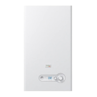
The recommended procedure for lling the condensate traps
before the start-up or after a prolonged shutdown is described
below:
− The oating ball of a dry trap is positioned at the bottom of
the trap, as shown below:
Floating ball
Fig. 15
Floating ball bottom
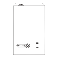
− To ll the trap with water, the top connection has to
be disconnected. First, unscrew and remove the hose
clamp. Then remove the plastic elbow from the top of the
condensate trap.
− Next, remove the condensate pressure switch line from the
upper hose barb on the condensate trap.
Hose clamp
Condensate
pressure
switch line
Plastic elbow
Fig. 16
Disconnected the top connection
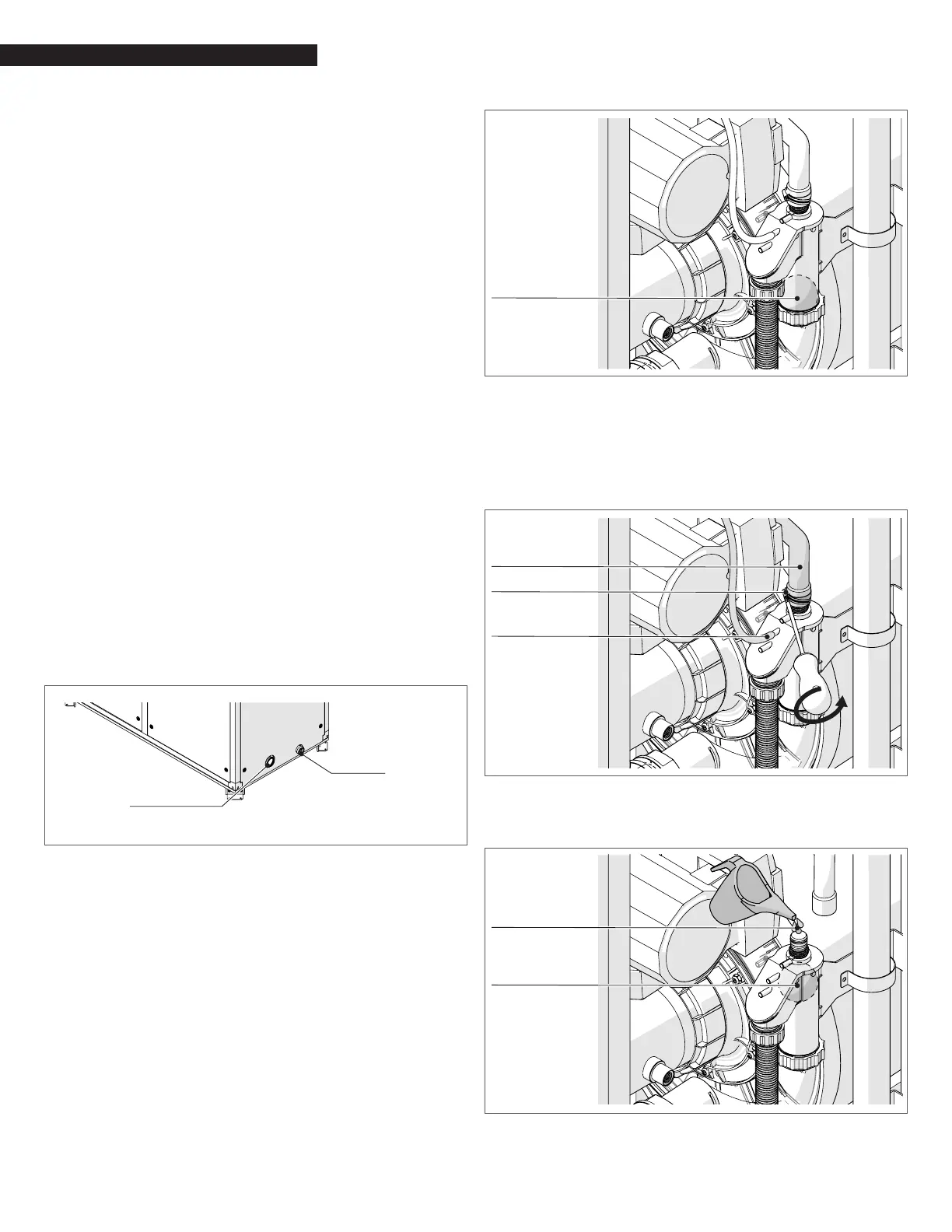
− Pour water into the top opening until the oating ball
reaches the top level of the trap.
Floating ball
Water
Fig. 17
Rell water
− Reconnect the pressure switch line to the upper hose barb
on the trap.