12
INSTALLATION
2.11 Gas supply piping
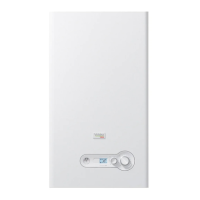
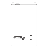
Array AR 1000, AR 1500 and AR 2000 boilers contain a 1.5 inch NPT
gas inlet connection on the top of the unit as shown in Fig. 9.
9
WARNING: Never use matches, candles, ames or other sourc-
es of ignition to check for gas leaks.
9
CAUTION: Many of the soaps used for gas pipe leak testing are
corrosive to metals. Therefore, piping must be rinsed thor-
oughly with clean water after leak checks have been com-
pleted.
NOTE: All gas piping must be arranged so that it does not interfere
with removal of any covers, inhibit service/maintenance, or re-
strict access between the unit and walls, or another unit.
− Prior to installation, all pipes should be de-burred and in-
ternally cleared of any scale, metal chips or other foreign
particles. Do Not install any exible connectors or unap-
proved gas ttings. Piping must be supported from the
oor, ceiling or walls only and must not be supported by
the unit.
− A suitable piping compound, approved for use with natural
gas, should be used. Any excess must be wiped off to pre-
vent clogging of components.
− To avoid unit damage when pressure testing gas piping,
isolate the unit from the gas supply piping. At no time
should the gas pressure applied to the unit exceed 20” W.C.
Leak test all external piping thoroughly using a soap and
water solution or suitable equivalent. The gas piping used
must meet all applicable codes.
− A sediment trap / drip leg must be installed on the gas sup-
ply piping.
− Installation of a union at the appliance gas line connection
is required for ease of service.
2.11.1 Gas Supply Specications
The gas supply input specications to the unit for Natural Gas are
as follows:
− The maximum static pressure to the unit must not exceed
20” W.C.
− The gas supply piping and pressure to the unit must be of
sufcient capacity to provide 1010 cfh for AR 1000, 1515 cfh
for AR 1500 and 2020 cfh for AR 2000, while maintaining the
recommended minimum gas pressure at 8” W.C. for burn-
ers operating at maximum capacity.
2.11.2 Manual Gas Shutoff Valve
A manual shut-off valve must be installed in the gas supply line
upstream of the boiler. Maximum allowable gas pressure to the
boiler is 20” W.C.
2.11.3 External Gas Supply Regulator
An external gas pressure regulator is required on the gas inlet pip-
ing under most conditions. Regulators must conform to the fol-
lowing specications:
− The external natural gas regulator must be capable of reg-
ulating
a) 100,000 - 1,000,000 BTU/HR for AR 1000
b) 100,000 - 1,500,000 BTU/HR for AR 1500
c) 100,000 - 2,000,000 BTU/HR for AR 2000
of natural gas while maintaining a recommended
minimum gas pressure of 8.0” W.C. to the unit.
− A regulator MUST be used when gas supply pressure will ex-
ceed 20” W.C.
The following are R’s recommendations for installation of gas
pressure regulator, unless superseded by state and local codes
and the regulator manufacturer’s specications:
− Horizontal installation of gas pressure regulators is recom-
mended unless stated otherwise by the regulator manu-
facturer. Consult the manufacturer for additional recom-
mendations and installation options.
− For all Array boilers, when installed horizontally the re-
quired distance between the gas pressure regulator and
the nearest pipe tting, elbow or valve is 10 feet.
− When pipe size reduction is required, use only bell reduc-
ers.
MASSACHUSETTS INSTALLATIONS ONLY
For Massachusetts installations, a mandatory external gas sup-
ply regulator must be installed. The gas supply regulator must be
properly vented to outdoors. Consult the local gas utility for de-
tailed requirements concerning venting of the supply gas regu-
lator.
The Commonwealth of Massachusettes prohibits the use of copper
tubing for the gas line.
NOTE: It is the responsibility of the customer to source and pur-
chase the appropriate gas regulator as described above.
2.11.4 Gas Type Conversion
The heating unit is factory preset for operating with natural gas.
This set-up can be changed using the conversion kits supplied by
the manufacturer, on demand.
9
DANGER: To prevent risks of personal injury and proper-
ty damage, this conversion shall only be performed by
a trained and certied installer in accordance with the
manufacturer’s instructions and all applicable codes
and requirements of the authority having jurisdiction.
If the information in these instructions is not followed exactly, or
the installation, adjustment, modication, operation or main-
tenance is carried out by an unqualied person, a re, explo-
sion or generation of large amounts of carbon monoxide may
result causing property damage, personal injury or loss of life.
Before carrying out electrical work, disconnect the appli-
ance from the power supply at the emergency shutoff switch
or by disengaging the heating system circuit breaker. Take
appropriate measures to prevent accidental reconnection.
The installer is responsible for the proper conversion of this
appliance. The conversion is not complete until the operation
of the converted appliance is checked as specied in these
instructions.
The gas-air ratio must always be set on the basis of a CO
2 or O2
reading taken at maximum nominal output and minimum nomi-
nal output using an electronic ue gas analyzer.
SWITCHING FROM NATURAL GAS TO LP
− Close the gas shutoff valve
− Disconnect the electric power supply from the boiler
9
WARNING: To avoid electrical shock, it is mandatory to discon-
nect the boiler from the power supply using a service discon-
nect external switch.
 Loading...