9
INSTALLATION
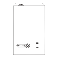
The unit must be installed on a concrete at oor, with no gra-
dient in any direction, to ensure proper condensate and water
drainage (see Fig. 7). If anchoring the unit, refer to Fig. 8 for anchor
locations.
Fig. 7
Array AR 1000, AR 1500 and AR 2000 Installation
58.2”
Fig. 8
Array AR 1000, AR 1500 and AR 2000 Anchoring bolts
2.5 Boiler location
− This boiler is suitable for indoor installations.
− To operate properly and safely this boiler requires a con-
tinuous supply of air for combustion. Install this boiler in a
clean, dry location with adequate air supply.
− Do not locate this boiler in an area where it will be subject
to freezing.
− The boiler should be located close to a oor drain in an
area where leakage from the appliance or connections will
not result in damage to the adjacent area or to lower oors
in the structure.
− DO NOT install this appliance in any location where gasoline
or ammable vapors are likely to be present.
− DO NOT install this appliance on top of carpet ooring.
− Appliance must be installed on a level oor.
− Maintain required clearances from combustible surfaces.
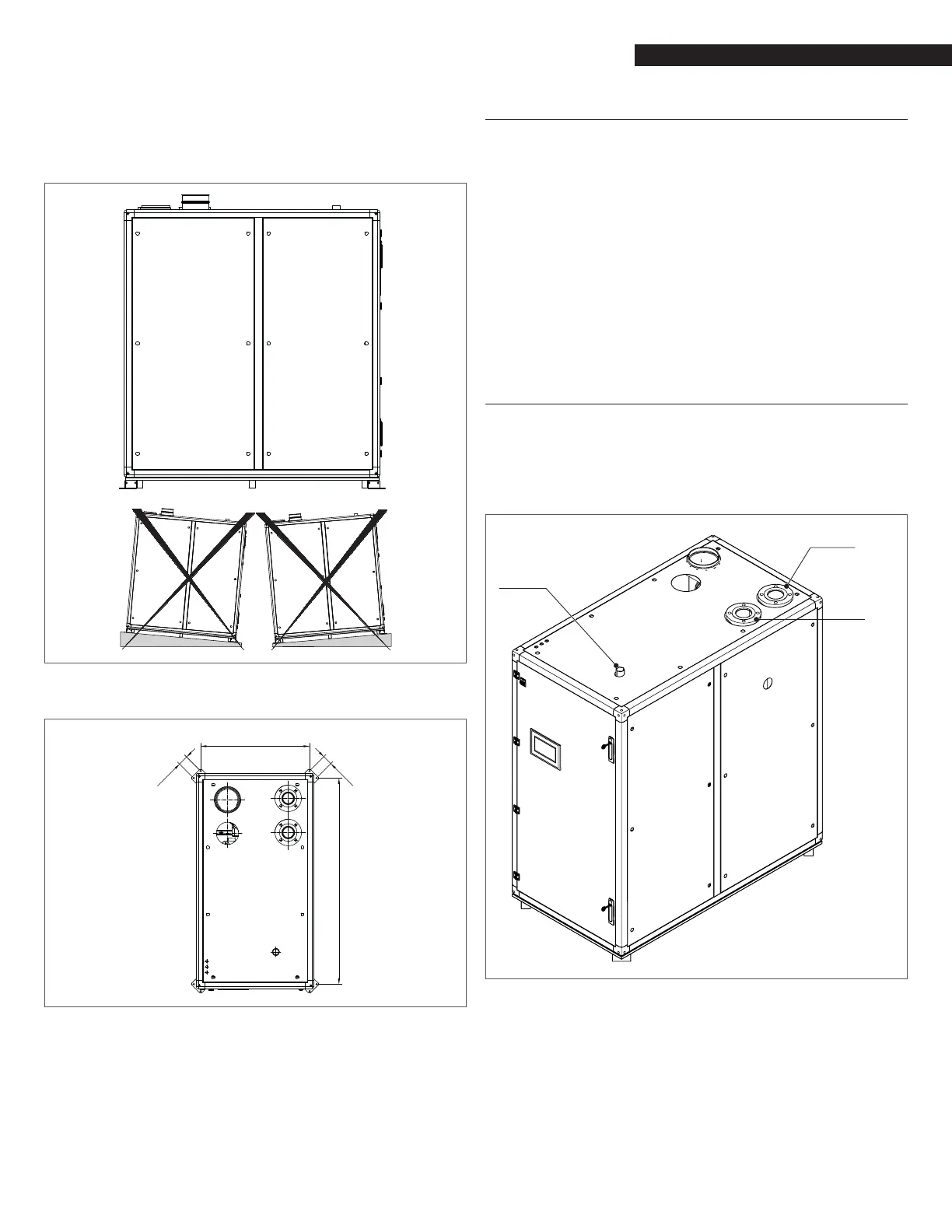
2.6 Supply and return piping
The Array Boiler utilizes 3” anges for models AR 1000 and AR 1500
and 4” anges for model AR 2000 for the water system supply and
return piping connections. The physical location of the supply and
return piping connections is on the top of the unit as shown in
Fig. 9.
Return
Water
Supply
Gas
connection
Fig. 9
Array AR 1000, AR 1500 and AR 2000 Connections