10
INSTALLATION
Excessive water hardness causing a lime buildup in the stainless
steel coils or tubes is not a fault of the appliance and is not cov-
ered by warranty. Water hardness must fall within the following
limits:
STEEL BOILERS - With furnace power > 500kBTU/h
Water used
for rst lling
Water with
system operating
ph 6 - 8 7.5 – 9.5
Hardness ppm < 50 < 50
Electrical Conduc-
tivity
ppm < 67
Chlorides ppm < 10
Sulphides ppm < 10
Nitrides ppm < 10
Oxygen in Solution ppm
Iron ppm < 0.5
− Use only untreated water to ll the system.
− Do not use TSP (tri-sodium phosphate).
− Do not use ll water treated with salt bedding type ex-
changers (ion exchanger).
− Never introduce non-approved boiler treatment or similar
additives.
− Consult a local water treatment specialist for recommenda-
tions if any of the above is outside the stated ranges.
− When using oxygen permeable PEX, the system must be
separated from the boiler by a heat exchanger.
− A correctly sized and working expansion vessel must be in-
stalled.
− Do not exceed the maximum permissible ow rate through
the boiler. Excessive ow can cause erosion damage to the
heat exchanger.
9
CAUTION: Before connecting the boiler to the heating system,
ush the heating system to remove sediment, ux, dirt, and
other foreign matter. The heat exchanger may be damaged by
sediment or corrosion.
9
CAUTION: Do not use cleaning uids that are not compatible
with the boiler materials, including acids (e.g. hydrochloric
acid and similar ones) at any concentration.
9
CAUTION: Introducing fresh water to the system increases the
oxygen presence and can cause corrosion of metallic compo-
nents. Immediately repair any drips or leaks in the system to
avoid constant introduction of air into the system.
9
CAUTION: Excessive uctuation in pressure changes in the sys-
tem can cause fatigue and stress on the heat exchanger. This
is detrimental to the integrity of the boiler and system com-
ponents, it is mandatory to maintain a constant operating
pressure.
9
CAUTION: For freeze protection use only propylene glycol, with
scale inhibitors, with a maximum volume [concentration] of
50% of glycol. Frost protection and inhibitor level has to be
checked annually during the regular scheduled maintenance
of the condensing boiler.
A minimum water pressure is required for optimum performance.
Minimum water pressure required: 7.25 psi (0.5 bar).
2.7 Low water cutoff
A low water cut off (LWCO) is installed on each boiler.
To check the functionality of LWCO go to the 905PB inner display,
access the Settings menu, select Test mode, and then click on
LWCO1. On the screen will appear the error “MN: Low Water Cutoff
Error”.
At this point press the reset button. The error will turn off.
2.8 High limit safety switch
A high limit safety switch is installed on each module of the boiler.
To simulate a high limit lockout at 208°F go to the 905PB inner
display, access the Settings menu, select Test mode, then click on
Max temp.
The control will display “MN: Max. Thermostat Lock Error”.
At this point press the reset button on the removable display to
restart the module.
The same test can be carried out as described at section “4.3.8
Module Test Screen” pag. 27.
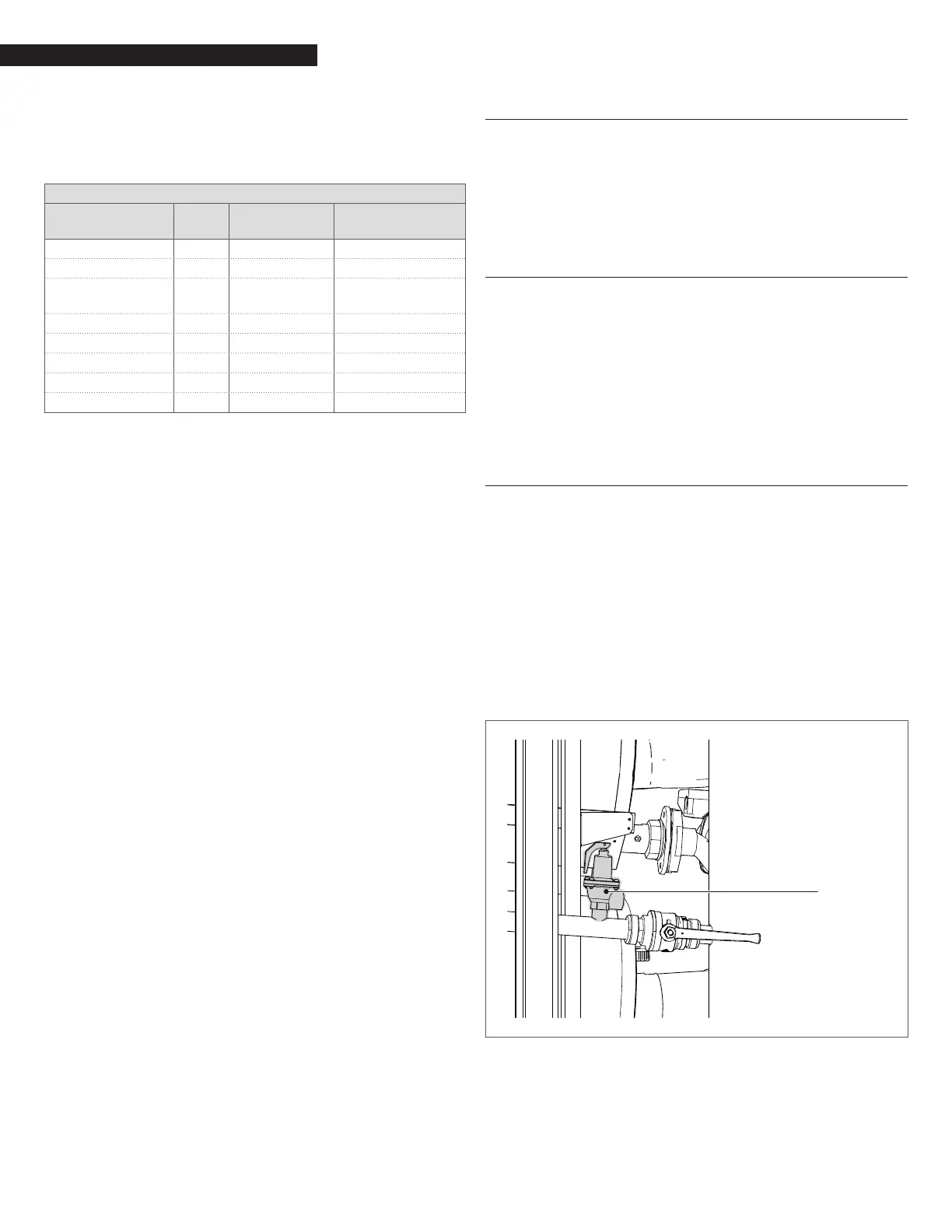
2.9 Pressure relief valve installation
ASME rated Pressure Relief Valves are factory installed in each Array
Boiler. The pressure rating for the relief valves is 75 PSI. The relief
valves are installed on each hot water horizontal manifold of the
boiler as shown in Fig. 10. The relief valves drain piping must be
connected to a nearby oor drain. In multiple unit installations
the discharge lines must not be manifolded together.
Each must be individually run to a suitable discharge location. Re-
lief valves should be manually operated at least once a year. If
a relief valve discharges periodically, this may be due to thermal
expansion in a closed water supply system.
Contact the water supplier or local plumbing inspector on how to
correct this situation.
Do not plug the relief valve.
75PSI Relief valve
(one for each module)
Fig. 10
Pressure Relief Valve Location
 Loading...