13
INSTALLATION
− Open the front panels
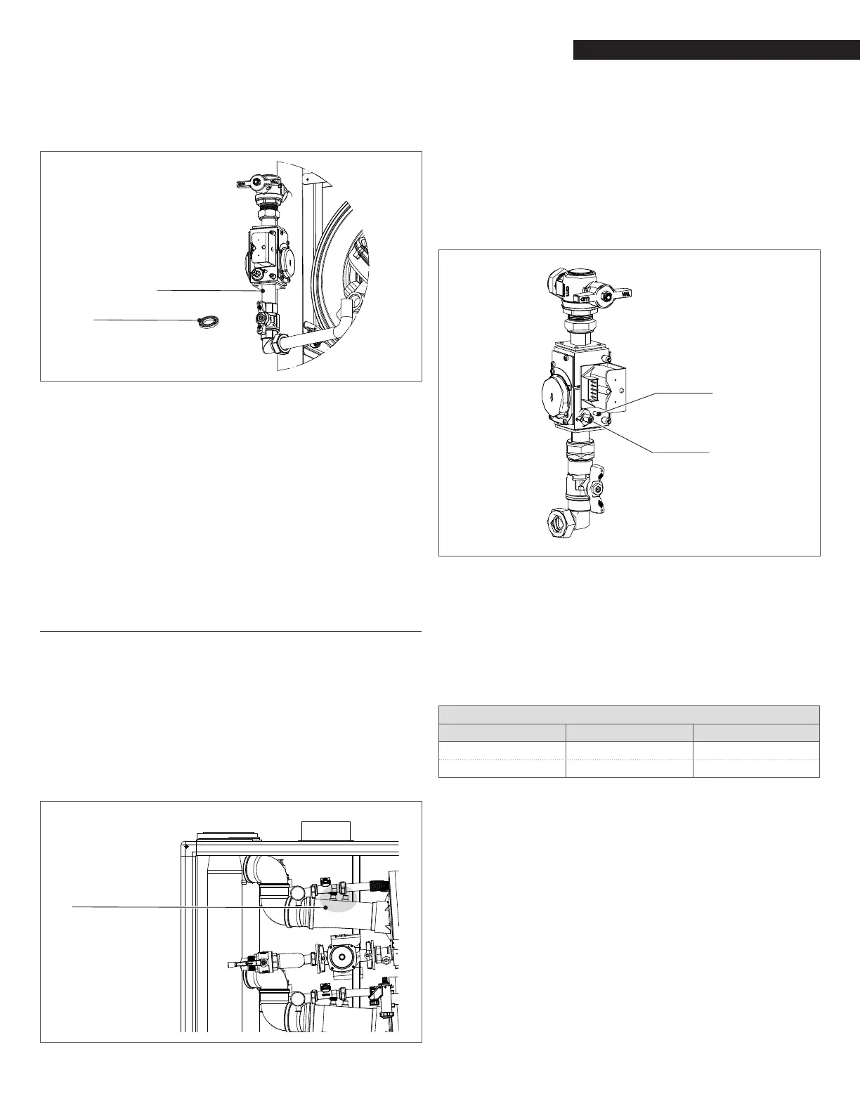
− Unscrew the swivel joint indicated in Fig. 14 to separate the
valve from the connection pipe with the fan
Swivel joint
LP Orifice
Fig. 14
Natural Gas to LP Gas Conversion
− Separating the two components, the hole where the gas
passes with its gasket can be accessed
− Place the provided metal orice (Fig. 14) between the two
gaskets (N° on orice: 9.5)
− Tighten the swivel joint
− Switch the main power supply to ON
− Use the 905PB inner display to enter in the parameter list
and change the parameter #95 (Gas Type) from “NG” to “LPG”
− Reopen the gas shut-off valve
− Adjust the CO
2 parameter as explained in next chapter
− Afx the gas type label from the gas conversion kit to the
appliance.
2.11.5 Adjusting and setting CO2 limits
− Insert a combustion analyzer probe into the test port
shown in Fig. 15
− Go to the Touchscreen and access the Module screen (as
described on ”4.3.4 Module Screen” pag. 26) relevant to the
module under analysis;
− Press “MODULE TEST” button;
− Press “HIGH POWER” button.
Wait 2 or 3 minutes to reach steady state conditions and record
the CO
2 value.
Test port of
the module
Fig. 15
Test Port for Combustion Analysis (available on each module)
To adjust the CO2 value at the maximum power turn the screw “A”
(rotate counter-clockwise to increase CO2) shown in Fig. 16, allen
type wrench is necessary for this adjustment.
Verify that the value of CO
2 is stable and is within the range indi-
cated in the following table (be careful to make small changes and
conrm that the value is stable before making additional adjust-
ment).
Press “LOW POWER”: the fan will run at the minimum speed.
Fig. 16
CO
2
Adjustment
To adjust the CO2 value at the minimum power turn the screw “B”
(rotate clockwise to increase CO2) shown in Fig. 16.
Verify that the value of CO
2 is stable and is within the range indi-
cated in the following table (be careful to make small changes and
conrm that the value is stable before making additional adjust-
ment).
Press “Reset” and the boiler return to the “stand by” mode.
Array Combustion Values
Gas Type Max. Fire CO
2% Min. Fire CO2%
Natural Gas 8.5 - 9.5 8.5 - 9.5
LP Gas 10.3 - 10.7 10.3 - 10.7