22
GENERAL
ENGLISH
0
0
1
2
3
4
5
6
7
8
0,5
1 1.5 2 2.5 3 3.5 4 0
0
10
20
30
40
50
60
0.5 1 1.5 2 2.5 3 3.5 4
CC4
CC3
CC2
CC1
CC1
CC2
CC3
CC4
PP3
PP3
CP3
PP2
PP2
PP1
PP1
CP2
CP1
CP3
CP2
CP1
Flow rate (m3/h)
Circulation unit head (m)
Flow rate (m3/h)
Power absorbed by circulation unit (W)
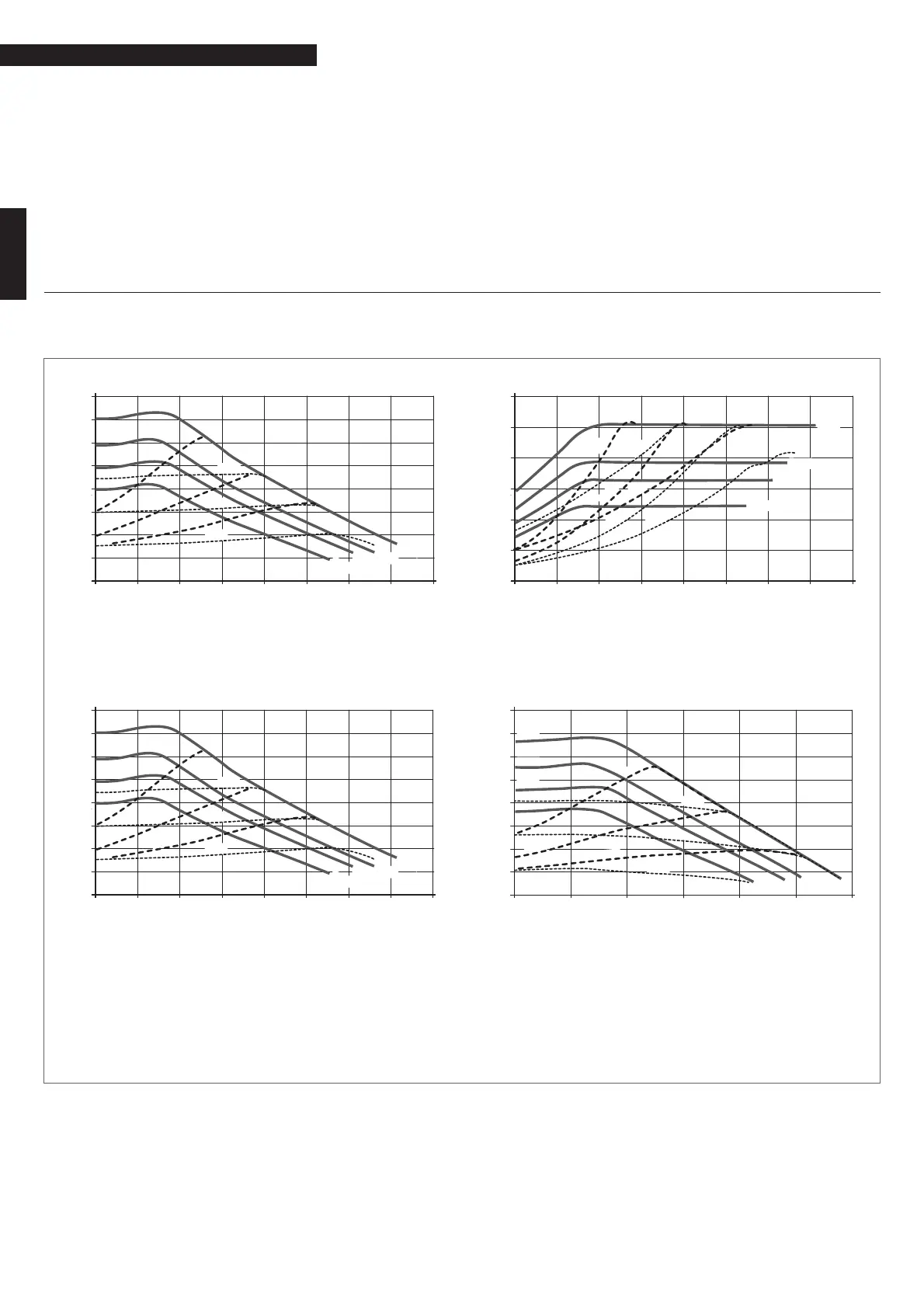
1.8 Circulation units
BAG
3
is equipped with high effi ciency electronically controlled circulation units. The performance data of these units to be used to
size the system is shown in the graph.
Available head of the circulation unit
Residual head available to the system
for BAG
3
AP
Residual head available to the system
for BAG
3
3 AP / BAG
3
2 AP
Power absorbed by the circulation unit
9
When starting up for the fi rst time and at least once a year,
it is advisable to check that the shaft of the circulation units
rotate.This is necessary because, especially after lengthy pe-
riods of inactivity, deposits and/or residue may stop it rotat-
ing freely.
0
Do not run the circulation unit without water.
9
If there are fl ow regulator devices in the low temperature
circuits (thermostatic, electrical or motorized zone valves,
etc.) it is recommended that the circulation unit is set to
"Proportional Head" and includes a differential by-pass on
the manifold.
PP1 LOW proportional head curve
PP2 AVERAGE proportional head curve
PP3 HIGH proportional head curve
CP1 LOW constant head curve
CP2 AVERAGE constant head curve
CP3 HIGH constant head curve
CC1 Curve 1 = 4 metres
CC2 Curve 2 = 5 metres
CC3 Curve 3 = 6 metres
CC4 Curve 4 MAX = 7 metres
0
0
1
2
3
4
5
6
7
8
0,5
11,5
Flow rate (m
3
/h)
Circulation unit head (m)
2 2,5 3 3,5 4
CC4
CC3
CC2
CC1
PP3
CP3
PP2
PP1
CP2
CP1
Flow rate (m
3
/h)
Circulation unit head (m)
00,511,522,53
CC1
CC2
CC3
CC4
PP3
PP2
PP1
CP3
CP2
CP1
0
1
2
3
4
5
6
7
8
Before any of the connections are made, all the piping must be
thoroughly fl ushed to remove any residue which could compro-
mise the proper functioning of the BAG
3
.
The plumbing connections to the boiler and the system must be
carried out rationally, as indicated in the fi gure.
Direct connections can be made using the female couplings on
the BAG
3
delivery and return pipes or cocks (not supplied) can
be fi tted on the system side. These cocks are very useful when
maintenance is carried out, as they allow just the BAG
3
to be
drained without having to drain the entire system.
9
Check that the expansion vessel on the boiler has suffi cient
capacity for the size of the system.
9
Ensure that the pipe connection holes from the BAG
3
to the
boiler are sealed.
 Loading...