INSTALLATION
24
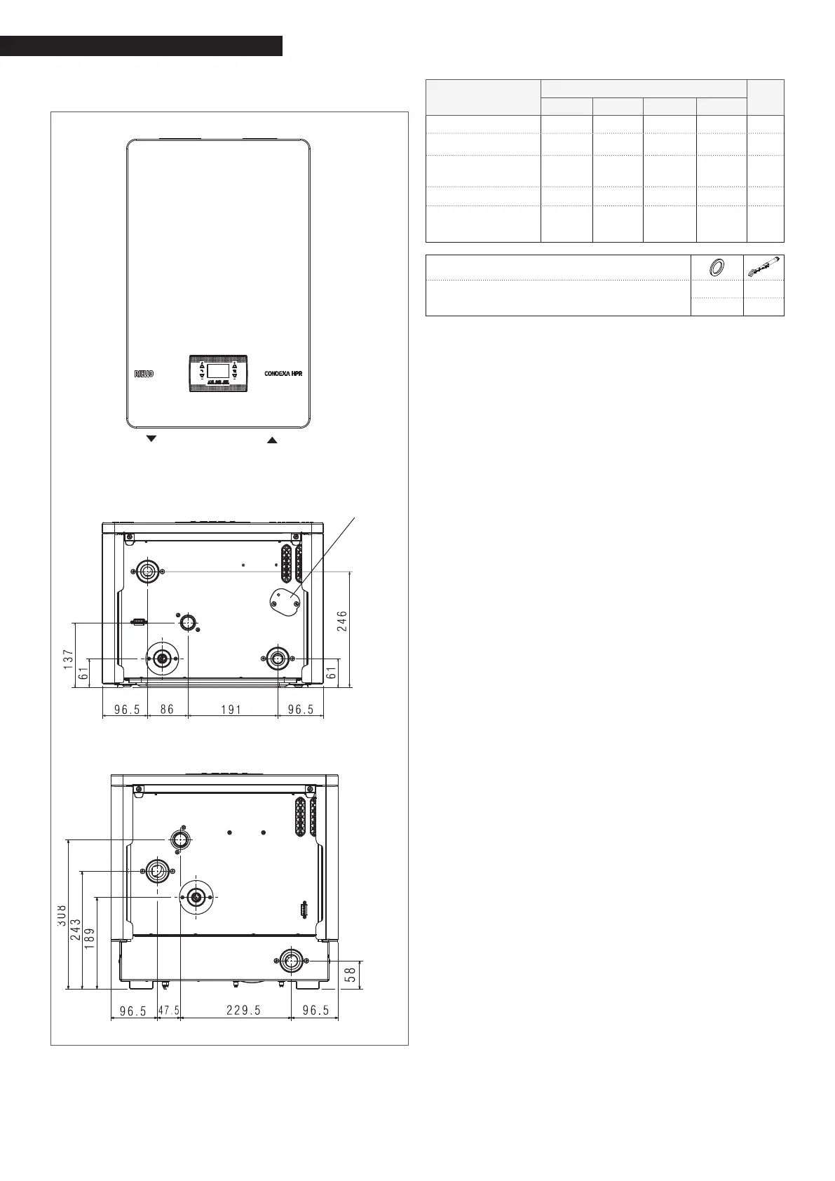
The dimensions and positioning of the thermal module
water ttings are shown in the table below.
diverting valve
connection
MI
RI
Condexa HPR 35-45
Condexa HPR 55-70
SC
Condexa HPR 35-45
Condexa HPR 55-70
G
G
SC
RI
RI
MI
MI
DESCRIPTION
Condexa HPR
35 45 55 70
MI (system delivery)
G 1" 1/2 M G 1" 1/2 M G 1" 1/2 M G 1" 1/2 M Ø
RI (system return) G 1" 1/2 M G 1" 1/2 M G 1" 1/2 M G 1" 1/2 M Ø
SC (condensate
discharge)
25 25 25 25
Ø
mm
G (gas inlet) G 3/4” M G 3/4” M G 3/4” M G 3/4” M Ø
diverter valve
connection
G 1” 1/2 M G 1” 1/2 M - - Ø
TIGHTENING TORQUE
Ø 3/4” 35Nm
Ø 1/2” 25Nm
9
Before connecting the boiler, the protection plugs
must removed from the delivery, return and con-
densate discharge pipes.
9
Before connecting the boiler, the system must be
cleaned. This step is vital when a replacement is
being made on a pre-existing system.
If the old generator is still installed in the system, when
cleaning you are advised to:
− add a de-scaling additive
− operate the system with the generator activated
for approx. 7 days
− discharge dirty system water and ush the system
out at least once with clean water
Repeat
the last step if the system is very dirty.
If the system is new or if the old generator is not tted
or available, use a pump to circulate the water with the
additive within the system for approx. 10 days, and then
carry out the nal washing procedure as described in
the previous point.
Once the cleaning operations have been completed, it is
advisable to add a suitable protective liquid to the sys-
tems water before installing the boiler.
To clean the internal water circuit of the heat exchanger,
contact the r
Aftersales Service.
a
Do not use incompatible liquid detergents, includ-
ing acids (for instance hydrochloric acid and simi-
lar) in any concentration.
a
Do not subject the heat exchanger to cyclical pres-
sure changes because fatigue stress is very danger-
ous for the system components.
 Loading...