INSTALLATION
28
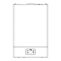
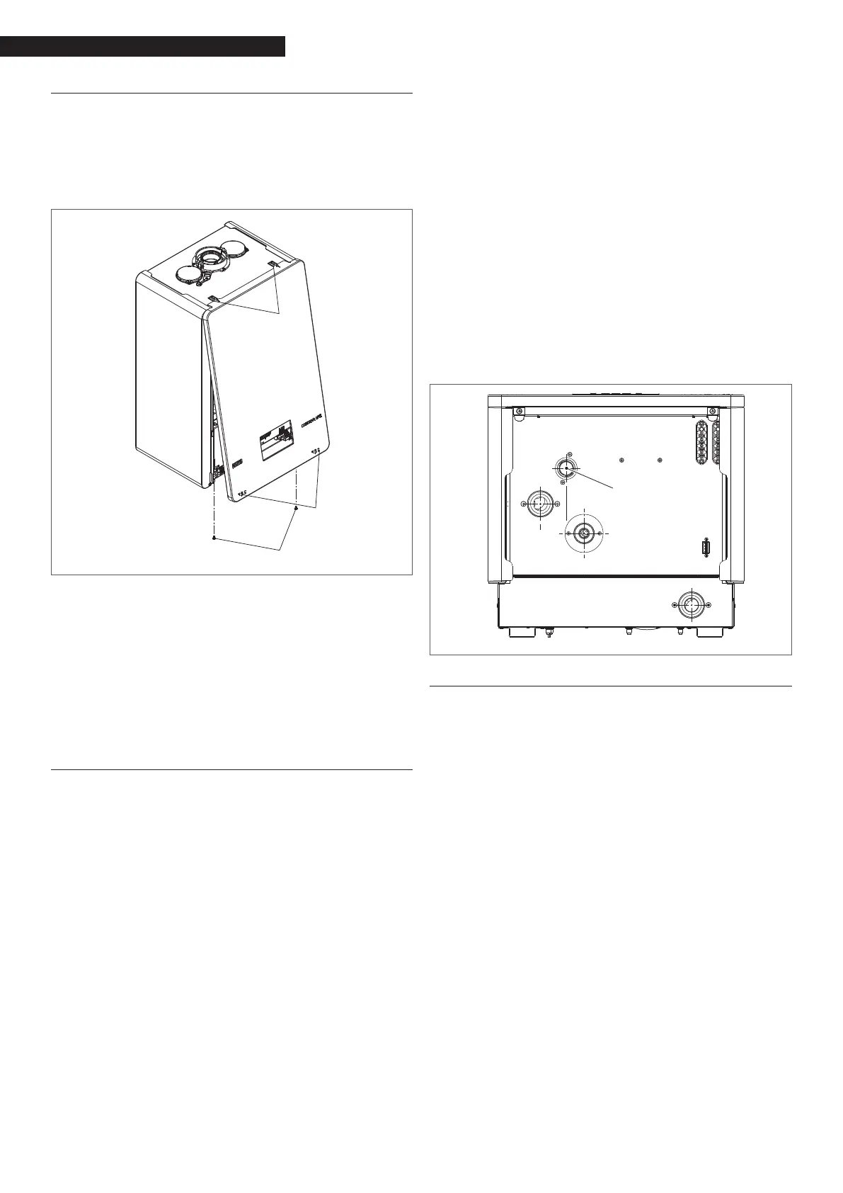
2.10 Removing the casing
To access the internal components, remove the casing as
explained below:
locate and loosen the 2 screws (A) xing the casing to
the boiler, levering the xing clips (C) and detaching
the lower part of the casing
raise the casing to release it from the upper tabs (B),
then remove it.
B
A
A
C
9
If the side panels are removed, ret them in their
initial position (referring to the label on the panel
itself).
9
If the front panel is damaged, it must be replaced.
9
The noise-absorbing panels in the front and side
walls ensure the airtight seal of the air supply duct
in relation to the place of installation.
9
It is therefore CRUCIAL to reposition the components
correctly to ensure the boiler seal.
2.11 Gas connections
The gas connection must be made respecting the instal-
lation regulations in force, and sized to ensure the cor-
rect gas delivery to the burner.
Before making the connection, check that:
9
The gas type is suitable for the appliance
9
If the appliance needs to be adapted for use with
another gasseous fuel, contact your local Aftersales
Service to have the necessary modications made.
These operations must not be carried out by the in-
staller under any circumstances.
9
The piping is thoroughly clean
9
The gas meter ow rate is capable of ensuring the
simultaneous use of all the appliances connected
to it. The appliance connection to the gas supply
line must be made in accordance with the current
regulations.
9
The intake pressure with the appliance OFF has the
following reference values:
− powered by methane gas: optimal pressure 20
mbar
− powered by LPG: optimal pressure 37 mbar
a
Do not use fuels other than those envisaged, for
any reason whatsoever.
While it is normal for the intake pressure to decrease while
the appliance is operating, it is a good idea to check that
there are no excessive pressure uctuations. In order to
limit the extent of these variations, the diameter of the
gas supply line must be dened according to the length
and the pressure drops of the line itself, from the meter
to the boiler.
9
If uctuations in the gas distribution pressure are
encountered, you are advised to install a pressure
stabiliser upstream of the appliance’s gas inlet. For
G31 gas supply, all the necessary precautions must
be taken to prevent the fuel gas from freezing in
the event of extremely low outdoor temperatures.
If the gas distribution network contains solid particles,
install a lter on the fuel supply line. When selecting it,
bear in mind that pressure drops due to the lter should
be as low as possible.
9
Once the installation is complete, check that the
joints are perfectly sealed.
GAS 3/4" M
Discharging the ue gases
2.12 Electrical wiring
The CONDEXA HPR thermal module leaves the factory ful-
ly wired, and only needs to be connected to the main
power supply and the system components.
9
It is mandatory:
− to use an omnipolar magnetothermal switch, a
line disconnector, complying with CEI-EN stand-
ards (contact opening of at least 3mm)
− to refer to the wiring diagrams in this booklet
when connecting the system components and
carrying out any electrical task.
9
The use of adaptors, multiple sockets and exten-
sions to power the appliance is not allowed.
9
Any work on the electrical system must only be car-
ried out by qualied personnel in compliance with
all legal provisions, paying special attention to the
safety regulations.
9
The supply cable is not supplied as standard. The
connection to the mains supply must be made us-
ing FROR 3G1.5 type cables (standardised by CEI 20-
27) or the equivalent.
9
Secure the cables with ties to ensure they are cor-
rectly positioned inside the appliance.
9
It is vital that the electricity cables and those for
the low voltage system components (room/heating
request thermostat, outdoor temperature sensors,
etc.) are separated
.
9
The installer is responsible for ensuring the appliance
 Loading...