INSTALLATION
29
is suitably earthed; the manufacturer will not be
liable for any damage resulting from an incorrect or
absent earth connection.
9
The length of the wires between the cable xing
point and the terminals must be such that, if the
cable slips out of its xing point, the live wires are
pulled taut prior to the earthing one. For this rea-
son, the earthing wire must be at least 2 cm longer
than the others.
9
The boiler can work with a phase-neutral or phase-
phase supply.
9
It is also advisable to respect the phase-neutral
connection (L-N).
9
Before connecting any external electrical compo-
nents (regulators, electric valves, climate control
probes, etc.) to the appliance, make sure their
electrical characteristics (voltage, absorption, ac-
celeration current) are compatible with the availa-
ble inputs and outputs.
9
The use of any type of tube for earthing the appli-
ance is forbidden.
a
It is forbidden to pull, detach or twist any electric
cables from the thermal module, even when the
latter is disconnected from the mains supply.
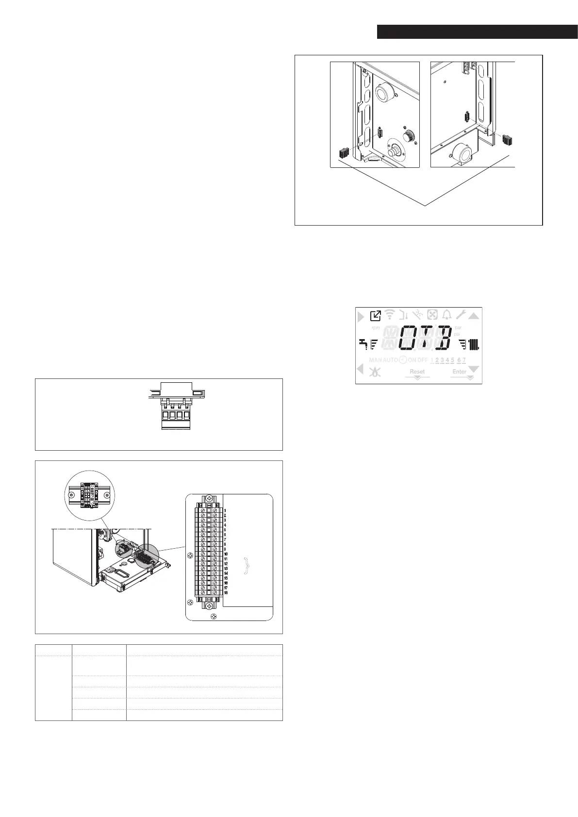
Low voltage connections
Make the low voltage connections as follows:
use the connectors supplied:
ModBus 4-pole connector for the BUS 485 signal (- A
B +)
-
A
B
+
GND
A
B
24V
ModBus CE4
connector
TA
OT+
TA
OT+
SE
SE
TB
TB
SB
SB
not used
not used
not used
GND
A
B
+ (24V)
not used
M02
}
only for
cascade
CE4 (- A B +) Bus 485
M02
TA
Room thermostat
(voltage-free contact)
OT+ Open therm
SE Outdoor temperature sensor
SB Storage tank probe
TB Storage tank thermostat
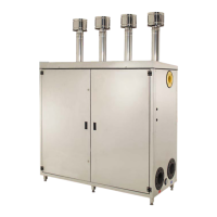
make the electrical connections using the required
connector, as indicated in the detailed drawing
after making the connections, insert the connector in
its counterpart.
CE4
9
You are advised to use conductors with a section no
larger than 0.5 mm
2
.
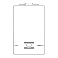
Connecting the OT+ remote control
NOTE: if an OT+ remote control is connected to the sys-
tem and
parameter P8.03= 1 (SERVICE), the boiler display will
appear as follows:
In particular, on the boil
er display:
it is no longer possible to set the boiler OFF/WINTER/SUM-
MER status (which can now be set via the OT+ remote
control)
it is no longer possible to set the DHW setpoint (which
can now be set via the OT+ remote control)
the DHW setpoint value is shown in the INFO menu
the heating setpoint set on the boiler display is only used
if there are requests from TA but no requests via the OT+
remote control if parameter:
P3.11 = 1
or
P3.11 = 0 and jumper on pin 1-2 of X21 closed
to activate the COMBUSTION CONTROL function with the
OT+ remote control connected, it is necessary to tempo-
rarily disable the connection by setting parameter P8.03
= 0 (remember to reset the value of this parameter after
using the function)
Note that it is not possible, with the OT+ remote control
connected, to change the value of parameters P4.12 to P4.23
from 0 to 1.
Note: the connection of an OT+ remote control is not
permitted if the system already contains BE16 interface
boards. For the same reason, BE16 boards cannot be con-
nected if there is already an OT+ device. In this case, the
system will give the following error message: <<OTER>>.
 Loading...