INSTALLATION
26
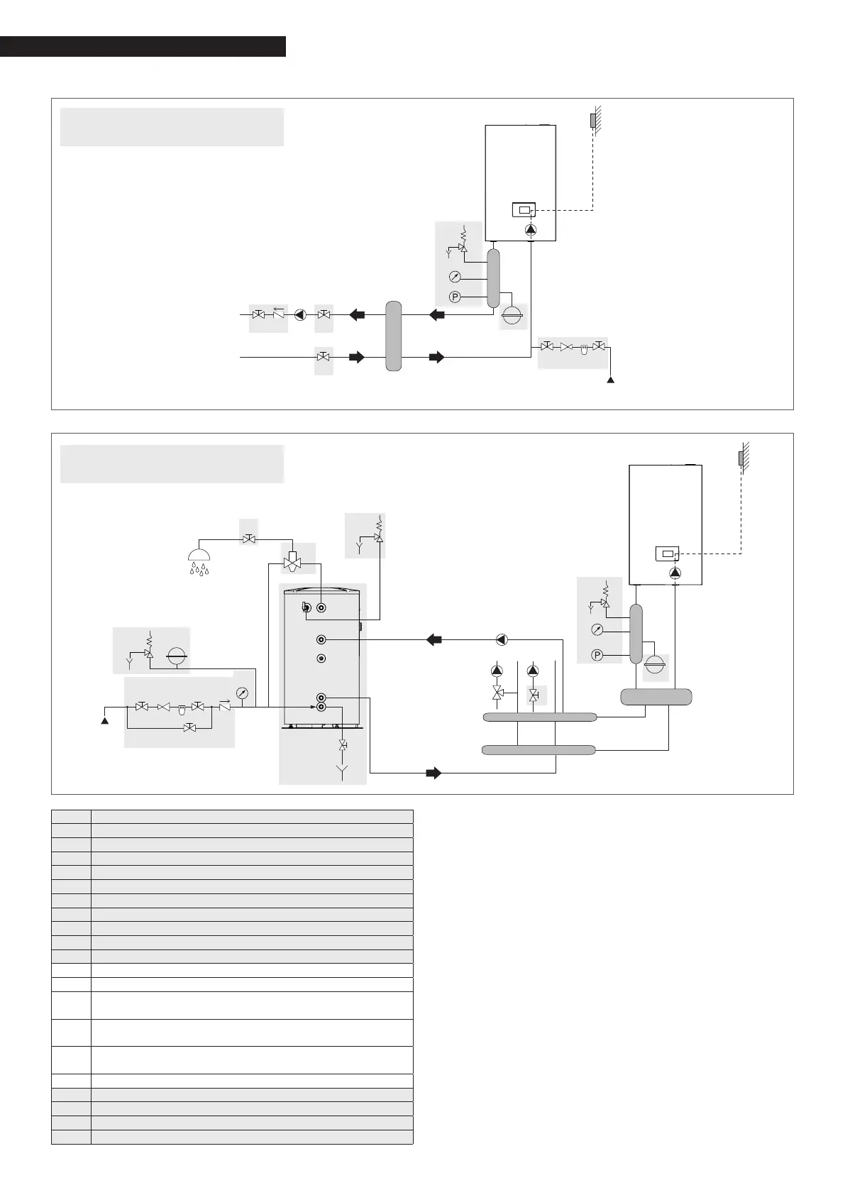
Layout 3: circuit with boiler connected to heating system via separator
2 11
1
15*
10 9 11
SE
MI
RI
EAF
4
5
6
7
8
13
Layout 4: circuit with boiler connected to DHW tank and heating system via separator
14
1
3
11
15*
16*
17*
1
1 10 9 1
1
2
6
5 4
7
1
5
6
4
5
6
7
8
EAF
UAC
SE
13
9
The domestic hot water and central heating circuits
must be completed with expansion vessels of ade-
quate capacity and suitable, correctly-sized safety
valves. The discharge of the safety valves and ap-
pliances must be connected to a suitable collection
and disposal system (see the price list catalogue for
compatible accessories).
9
The selection and installation of the system com-
ponents is the responsibility of the installer, who
must respect the standards of good practice and
current legislation.
9
Special supply/make-up water must be conditioned
using suitable treatment systems.
a
It is forbidden to operate the boiler and circulators
without water.
Components NOT managed
directly by the boiler
Components NOT managed
directly by the boiler
1 Disconnector valve
2 Non-return valve
3 Anti-burn mixer valve
4 Expansion vessel
5 Safety valve
6 Discharge
7 Pressure gauge
8 Minimum pressure switch
9 Softener filter
10 Pressure reducer
11 Storage tank
13 Boiler circulator
14 Storage tank circulator
15
Direct zone circulator (*managed by boiler with
specic accessory)
16
Mixed zone circulator (*managed by boiler with
specic accessory)
17
Mixing valve (*managed by boiler with specic
accessory)
SE Outdoor temperature sensor
MI High-temperature system delivery
RI High-temperature system return
EAF Cold water inlet
UAC DHW outlet
 Loading...