1541
2
GB
WORKING RANGE
(as EN 267)
DIMENSIONS
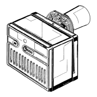
MOUNTING THE BURNER
0.6
0
0.2
0.4
Pressure in the combustion
chamber – mbar
1 1.5 2.52 Gas oil output - kg/h
14 20 26 30 Thermal power - kW
D5603
0.1
0.3
0.5
16 18 22 24 2812
Flange Burner
252
88 203
130
=
19
45°
215
11
164
D5509
=
180
75 72
150
45°
ø 87
It is necessary that the insulating gasket
(9, fig. 1) is placed between the boiler door
and the burner flange.
This insulating gasket has six holes,
which, if necessary, can be modified as
shown on the drawing on the right.
Verify that the installed
burner is lightly leaned
towards the button.
(See figure 2).
The burner is designed to
allow entry of the flexible
oil-lines on either side of
the burner.
D5242
D5218
Fig. 2
BURNER FIXING
S7386