2903334
10
SETTING UP THE BURNER
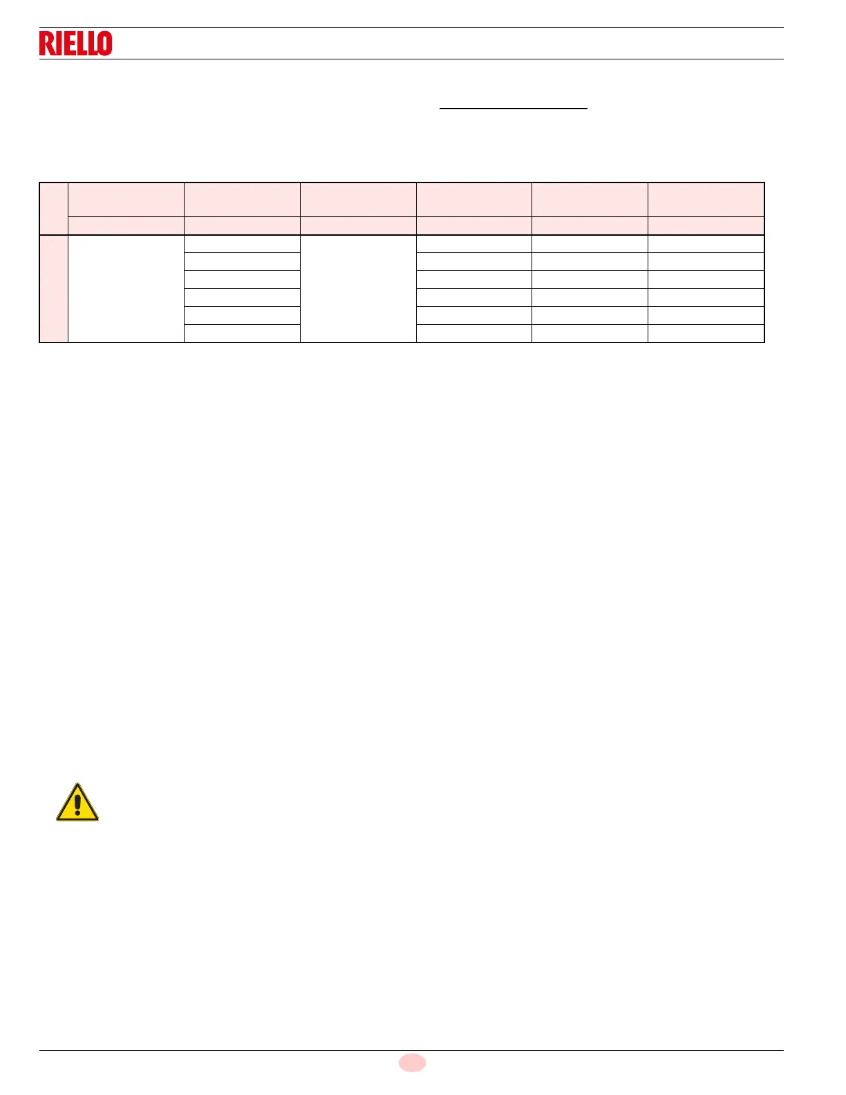
After burner output has been determined, use TABLE 1 below AS AN INITIAL GUIDE for burner settings.
All settings in this table were obtained under the following conditions.
0 (zero) draft in the combustion zone;
Standard lab test boiler;
Inlet gas pressure range as in table 1;
Steady state (HOT) operating conditions.
Burner input decreases with increasing the combustion chamber pressure.
Once installed, a higher or lower burner input can be achieved by raising or lowering the manifold pressure from - 0.5” wc.
to +1.5” wc. Pressure changes can only be made when the burner is running. The typical working manifold pressure is 3.5”
wc. (both for natuaral gas and propane).
SAFETY TEST - WITH GAS BALL VALVE CLOSED
It is fundamental to ensure the correct execution of the electrical connections between the gas solenoid valves and the burner to perform
safely the commissioning.
For this purpose, after checking that the connections have been carried out in accordance with the burner's electrical diagrams, an ignition
cycle with closed gas ball valve -dry test- must be performed.
1 The manual ball gas valve must be closed
2 The electrical contacts of the burner limit switch need to be closed
3 Ensures closed the contact of the low gas pressure switch
4 Make a trial for burner ignition.
The start-up cycle must be as follows:
– Starting the fan for pre-ventilation
– Performing the gas valve seal control, if provided
– Completion of pre-ventilation
– Arrival of the ignition point
– Power supply of the ignition transformer
– Electrical Supply of solenoid gas valves
Since the manual gas ball valve is closed, the burner will not light up and its control box will go to a safety lockout condition.
The actual electrical supply of the solenoid gas valves can be verified by inserting a tester. Some valves are equipped with light signals
(or close/open position indicator) that turn on at the same time as their power supply.
STEP BY STEP PROCEDURE
1) Set air gate. See AIR GATE ADJUSTMENT on page 11.
2) Set gas diaphragm and combustion head.
See DIAPHRAGM INSTALLATION AND COMBUSTION HEAD SETTING on page 12.
3) Set the manifold pressure using the following method.
a) In order to determine existing manifold pressure, start the burner.
At the end of the prepurge cycle (approx. 30s), the gas valve is energized.
During the 5 sec. trial for ignition, note the observed manifold pressure. If the burner lights and continues to
run, go to step (d).
b) Compare the observed manifold pressure from step (a) to the required value from TABLE 1.
Gas inlet
pressure range
Diaphragm
Manifold
gas pressure
Burner
output
Head
setting
Air gate
setting
“wc Marking “wc Btu/hr Nocth Notch
NATURAL GAS
5.0 - 7.0
C1
3.5
170,000 0 1.1
C2 201,199 1 1.6
C3 243,674 2 1.95
C4 301,426 3 2.3
C5 366,629 4 2.5
C6 400,000 4 3.0
IF THE ELECTRICAL SUPPLY OF THE GAS VALVES OCCURS AT UNEXPECTED TIMES, DO NOT OPEN MANUAL
GAS BALL VALVE, SWITCH OFF POWER LINE; CHECK THE WIRES; CORRECT THE ERRORS AND REPEAT THE
COMPLETE TEST.
 Loading...