1915
5
GB
3.4 ELECTRICAL WIRING
CONTROL BOX
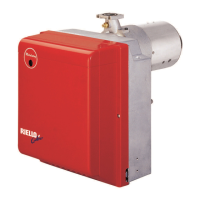
To remove the control-box from the burner, loosen screw (A, fig. 10)
and pull to the arrow direction, after removing all components, the
7pin plug and earth wire.
In case of disassembly of the control box, retighten the screw
(A) with a torque wrench setting of 1 – 1.2 Nm.
S7072
Fig. 10
A
D1913
ESEGUITO IN FABBRICA
7 pin plug
7 pole socket
Black
White
Capacitor
Main switch
T6A
Motor
Blue
Oil valve
Hour counter
(230V - 0.
1A
max.)
Limit thermostat
Remote lock-out signal
(230V - 0.5A max.)
Ignition
electrodes
Brown
Burner-earth
CARRIED-OUT IN THE FACTORY
552SE
CONTROL BOX
Photoresistance
PE L N
~
50Hz 230V
Blue
● (See page 4). Connect the automatic shut-off
device (230V - 0.5A max.) to the clamps N - B4
of the 7 pin plug.
TESTING
Check the shut-down of the burner by opening
the thermostats and the lock-out by darkening
the photoresistance.
Safety thermostat
ATTENTION:
‰
Do not swap neutral and phase over, follow the diagram shown carefully and carry out a good earth con-
nection.
‰
The section of the conductors must be at least 1mm². (Unless requested otherwise by local standards and legislation).
‰
The electrical wiring carried out by the installer must be in compliance with the rules in force in the country.
 Loading...