5
ENGLISH
EN
b
The earth conductor must be a couple of cm longer than the others.
b
To create the seal of the boiler use a clamp and tighten it on the cable grommet used
.
The boiler can operate with a phase-neutral or phase-phase power supply.
It is forbidden to use gas and/or water pipes to earth electrical appliances.
Use the power cable supplied to connect the boiler to the mains power supply. If the power
cable has to be replaced, use a HAR H05V2V2-F, 3 x 0.75mm² cable, Ø max external 7 mm.
2.5 Gas connection
The connection of the gas supply must be carried out in compliance with current installation
standards. Before carrying out the connection, check that the type of gas is that for which
the appliance is set up.
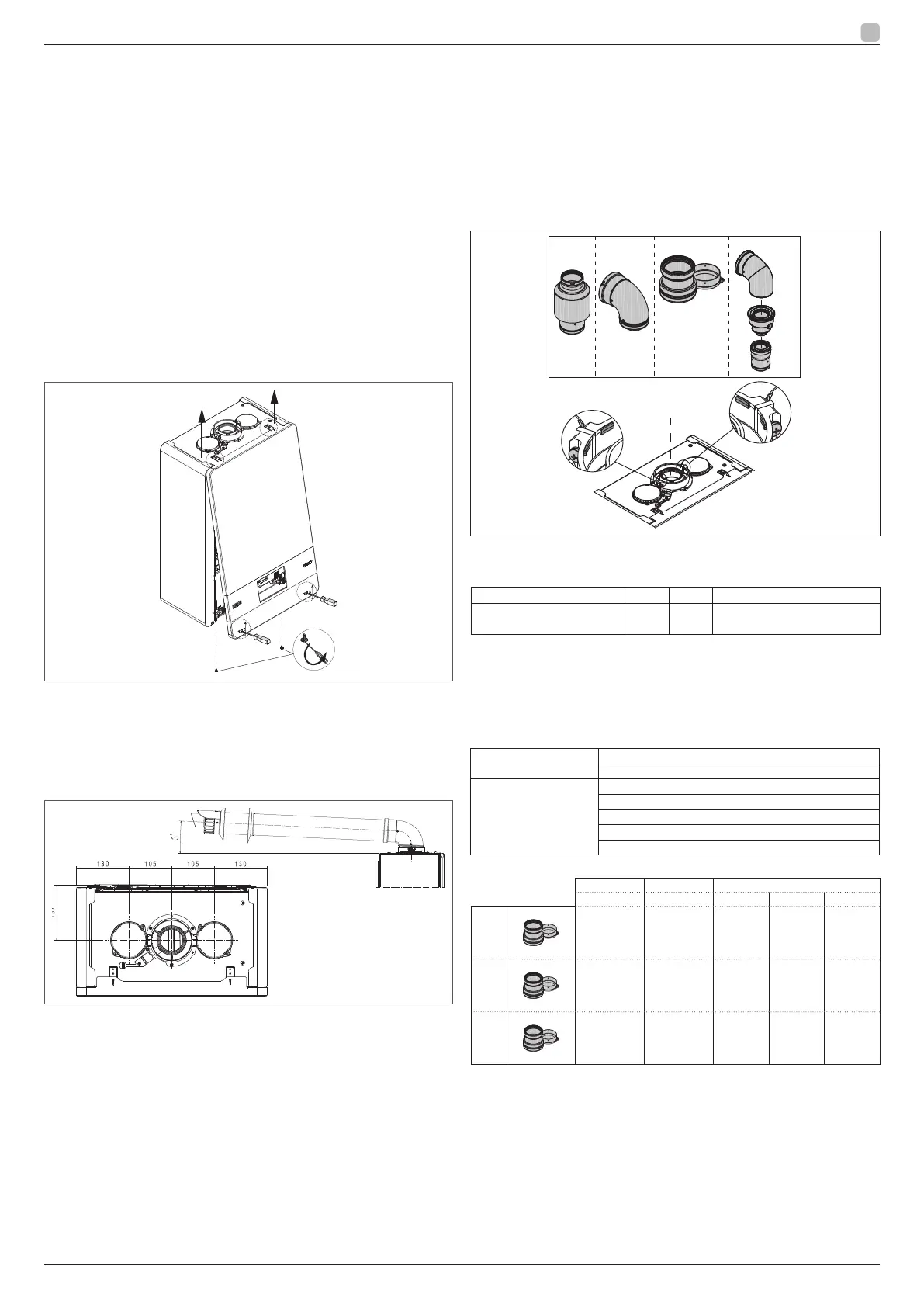
2.6 Removing the casing
To access the components inside, remove the casing as shown in the gure.
b
If removing the side panels, put them back in their initial position, referring to the
adhesive label on its wall.
b
If the front panel is damaged it must be replaced.
b
The noise absorbing panels inside the front and side walls ensure the airtight seal for the
air supply duct in the installation environment.
b
It is therefore CRUCIAL after the dismantling operations to correctly reposition the
components to ensure the boiler's seal is effective.
B
B
C
C
A
2.7 Flue gas exhaust and combustion air suction
To evacuate the combustion products, refer to UNI 7129-7131. Always comply with
local standards of the Fire Department, the Gas Company and with possible municipal
dispositions. It is essential for the evacuation of the ue gases and the adduction of the
boiler's combustion air that only original pipes be used (except C6) and that the connection
is made correctly as shown in the instructions provided with the ue gases accessories.
A single ue can be connected to several appliances provided that every appliance is the
condensing type.
b
The straight length includes the rst bend (connection into the boiler), terminals
and joints. An exception is made for the vertical Ø 60-100 mm coaxial pipe, whose
straight length excludes bends.
b
To ensure greater installation safety, x the ducts to the wall (wall or ceiling) using
special xing brackets to be positioned at each joint, at a distance such as not to
exceed the length of each individual extension and immediately before and after
each change of direction (curve).
b
The boiler is supplied without the ue gas exhaust/air suction kit, since it is possible
to use the accessories for condensing appliances that best t the installation
characteristics (see RIELLO catalogue).
b
The maximum lengths of the pipes refer to the ue accessories available in the
RIELLO catalogue.
b
It is compulsory to use specic pipes.
b
The non insulated ue gas outlet pipes are potential sources of danger.
b
The use of a longer pipe causes a loss of output of the boiler.
b
The exhaust pipes can face in the direction most suited to the installation
requirements.
b
As envisaged by current legislation, the boiler is designed to take in and dispose of
ue gas condensate and/or meteoric water condensate deriving from the ue gas
discharge system using its own siphon.
b
If a condensate relaunch pump is installed, check the technical data (provided by the
manufacturer) regarding output, to ensure it operates correctly.
- Position the discharge pipe so that the connection sits fully up against the ugases turret
of the boiler.
- After positioning it, make sure the 4 notches (A) slip into the groove (B).
- Fully tighten the screws (C) that hold the two ange locking terminals, so thbend itself is
restrained held in place.
B
B
B
B23P-B53P Ø60-100 Ø80-80
A
A
C
C
B
B
Ø80-125
b
If the Ø 60-100 to Ø 80-80 splitter kit is used instead of the twin pipe system, there
is a loss in the maximum lengths as shown in the table.
Ø50 Ø60 Ø80
Loss of length (m) 0.5 1.2
5.5 for flue gases pipe
7.5 for air pipe
Twin pipes with Ø 80 pipework Ø50 - Ø60 - Ø80)
Thanks to the boiler characteristics, a Ø80 ue gas exhaust pipe can be connected to
the Ø50 - Ø60 - Ø80 piping ranges.
b
For the pipe, you are advised to make a project calculation in order to respect the
relevant regulations in force.
The table shows the standard congurations allowed.
Air suction
1 Bend 90° Ø 80
4.5m pipe Ø80
Flue gas discharge
1 Bend 90° Ø 80
4.5m pipe Ø80
Reduction from Ø80 to Ø50 from Ø80 to Ø60
Flue base bend 90°, Ø50 or Ø60 or Ø80
For ducting pipe lengths see table
The boilers are factory set to:
CH rpm DHW rpm Max length pipes (m)
Ø50 Ø60 Ø80
25 KIS
6.200 7.600 5 18 98
30 KIS
5.800 6.900 2 11 53
35 KIS
7.300 7.800 2 11 57
Should greater lengths be required, compensate the pressure drop with an increase in the
r.p.m.of the fan, as shown in the adjustments table, to provide the rated heat input, referring
to paragraph “3.9 Adjustments”.
b
The minimum calibration should not be modied.
 Loading...