3008
1
GB
3002949
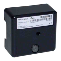
CONTROL BOX MG569
3002967
The new control box MG569 is installed on either single or dou-
ble stage burners
, (see fig. 1).
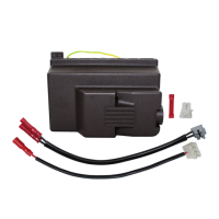
EQUIPMENT
Control box MG569 . . . . . . . . . . . . . . . . . . . . . . . . . . . . . N° 1
Leads RS . . . . . . . . . . . . . . . . . . . . . . . . . . . . . . . . . . . . N° 1
Leads SO . . . . . . . . . . . . . . . . . . . . . . . . . . . . . . . . . . . . N° 1
Protection V2 . . . . . . . . . . . . . . . . . . . . . . . . . . . . . . . . . N° 1
Assembly connection (only for code 3002949) . . . . . . . . . N° 1
Instruction . . . . . . . . . . . . . . . . . . . . . . . . . . . . . . . . . . . . N° 1
The assembly connection (fig. 6, page 2) must be used only if
a control box model 525SE/G, 566SE, 566SE Rev. 1 and
566SE Rev. 2 needs to be replaced.
INSTALLATION
Trained personnel must carry out the substitu-
tion of the control box.
It is necessary to switch off the main power sup-
ply before effecting any substitution.
To install the new MG569 control box, it is necessary
to use the diagram below.
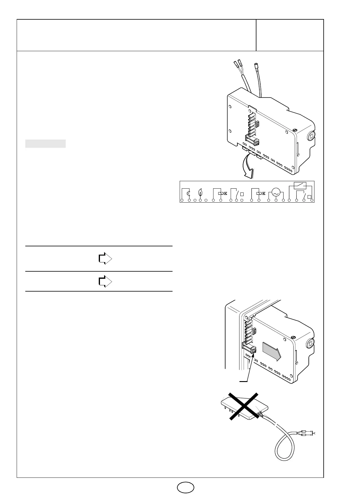
To install, proceed as follows:
®
Unscrew the fixing screws and remove the burner cover.
®
Disconnect all connections, the 7-pin plug, the ioniza-
tion probe, the H.T. lead and the earth wire from the
control box.
®
Remove the control box from the burner by unscrewing
the screws (A, fig. 3) and pull in the direction of the ar-
row.
®
Install the new control box supplied by fastening it to the
burner by the screw (A, fig. 3), with a torque wrench set-
ting of 1 – 1.2 Nm.
®
Reconnect all connections, the 7-pin plug and the earth
wire.
REMOTE RESET CONNECTION, (fig. 4)
If the burner has a remote reset, you must proceed as fol-
lows:
®
Cut the existing socket-connection.
®
Carry out the new connection (RS, see electrical wiring
page 3).
®
Connect a button at 20 m. max.
RS SO
Fig. 1
E9249
Fig. 2
ATTENTION
N L2
R
=
=
C
S2
N
2
S1
A
M
B
A
N
1
G
E9263
SO PA SMMVV2 V1RS PG
KEY TO LAY-OUT, (fig. 2)
SM-Servomotor (for burners designed)
PG - Gas pressure switch
MV- Motor
V1 -1
st
stage valve
PA - Air pressure switch
V2 -Protection
SO - Ionisation probe
RS - Remote reset
MG569
568 - 569
566SE Rev. 3
MG569
525SE/G - 566SE
566SE Rev. 1 and Rev. 2
MG569 + Assem-
bly connection
Fig. 3
E9250
A
E9242
Fig. 4