3002949
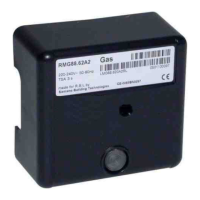
APPARECCHIATURA MG569
1
I
3002967
2903008 (1)
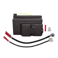
La nuova apparecchiatura
MG569
viene installata su brucia-
tori monostadio e bistadio, (vedi fig. 1).
MATERIALE A CORREDO
Apparecchiatura MG569 . . . . . . . . . . . . . . . . . . . . . . . . .N° 1
Collegamento RS . . . . . . . . . . . . . . . . . . . . . . . . . . . . . .N° 1
Collegamento SO . . . . . . . . . . . . . . . . . . . . . . . . . . . . . .N° 1
Protezione V2 . . . . . . . . . . . . . . . . . . . . . . . . . . . . . . . . .N° 1
Gruppo collegamenti (solo per cod. 3002949) . . . . . . . . .N° 1
Istruzione . . . . . . . . . . . . . . . . . . . . . . . . . . . . . . . . . . . .N° 1
Il gruppo collegamenti (fig. 6, pag. 2) deve essere utilizzato
solamente nel caso in cui sia necessario sostituire un’apparec-
chiatura modello 525SE/G, 566SE, 566SE REV. 1 e 566SE
REV. 2.
INSTALLAZIONE
La sostituzione dell’apparecchiatura deve essere
eseguita da personale abilitato.
Prima di effettuare qualsiasi operazione di sosti-
tuzione è necessario staccare l’alimentazione
generale all’impianto.
E’ necessario utilizzare lo schema sottoriportato per
l’installazione della nuova apparecchiatura MG569.
Per l’installazione eseguire le seguenti operazioni:
®
Svitare le viti di fissaggio e togliere il cofano dal brucia-
tore.
®
Sconnettere tutti i componenti, la spina a 7 poli il con-
nettore sonda, i cavi di alta tensione ed il filo di terra
dall’apparecchiatura.
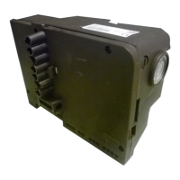
®
Scollegare l’apparecchiatura dal bruciatore svitando la
vite (A, fig. 3) e tirare nel senso della freccia.
®
Installare la nuova apprecchiatura fornita a corredo
fissandola al bruciatore mediante la vite (A, fig. 3) con
coppia di serraggio da 1 ÷ 1,2 Nm.
®
Connettere tutti i suddetti collegamenti,
la spina 7 poli
e il filo di terra.
CONNESSIONE SBLOCCO REMOTO, (fig. 4)
Nel caso in cui il bruciatore sia previsto di sblocco
remoto, è necessario seguire le seguenti indicazioni:
®
Tagliare il collegamento-presa esistente.
®
Eseguire la connessione con il nuovo collegamento
(RS, vedi schemi elettrici pag. 3).
®
Connettere un pulsante a max. 20 metri.
RS SO
Fig. 1
E9249
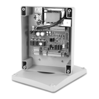
Fig. 2
ATTENZIONE
N L2
R
=
=
C
S2
N
2
S1
A
M
B
A
N
1
G
E9263
SO PA SMMVV2 V1RS PG
LEGENDA, (fig. 2)
SM-Servomotore (per bruciatori predisposti)
PG - Pressostato gas
MV- Motore
V1 - Elettrovalvola 1° stadio
PA - Pressostato aria
V2 - Protezione
SO - Sonda ionizzazione
RS - Sblocco remoto
MG569
568 - 569
566SE Rev. 3
MG569
525SE/G - 566SE
566SE Rev. 1 e Rev. 2
MG569 + Gruppo
collegamenti
Fig. 3
E9250
A
E9242
Fig. 4