3008
2
GB
ASSEMBLY CONNECTION
For burners with control boxes 525SE/G, 566SE, 566SE
Rev. 1 and Rev. 2, make as following:
®
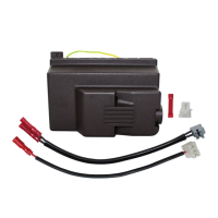
Remove the suppressor connection (fig. 5);
®
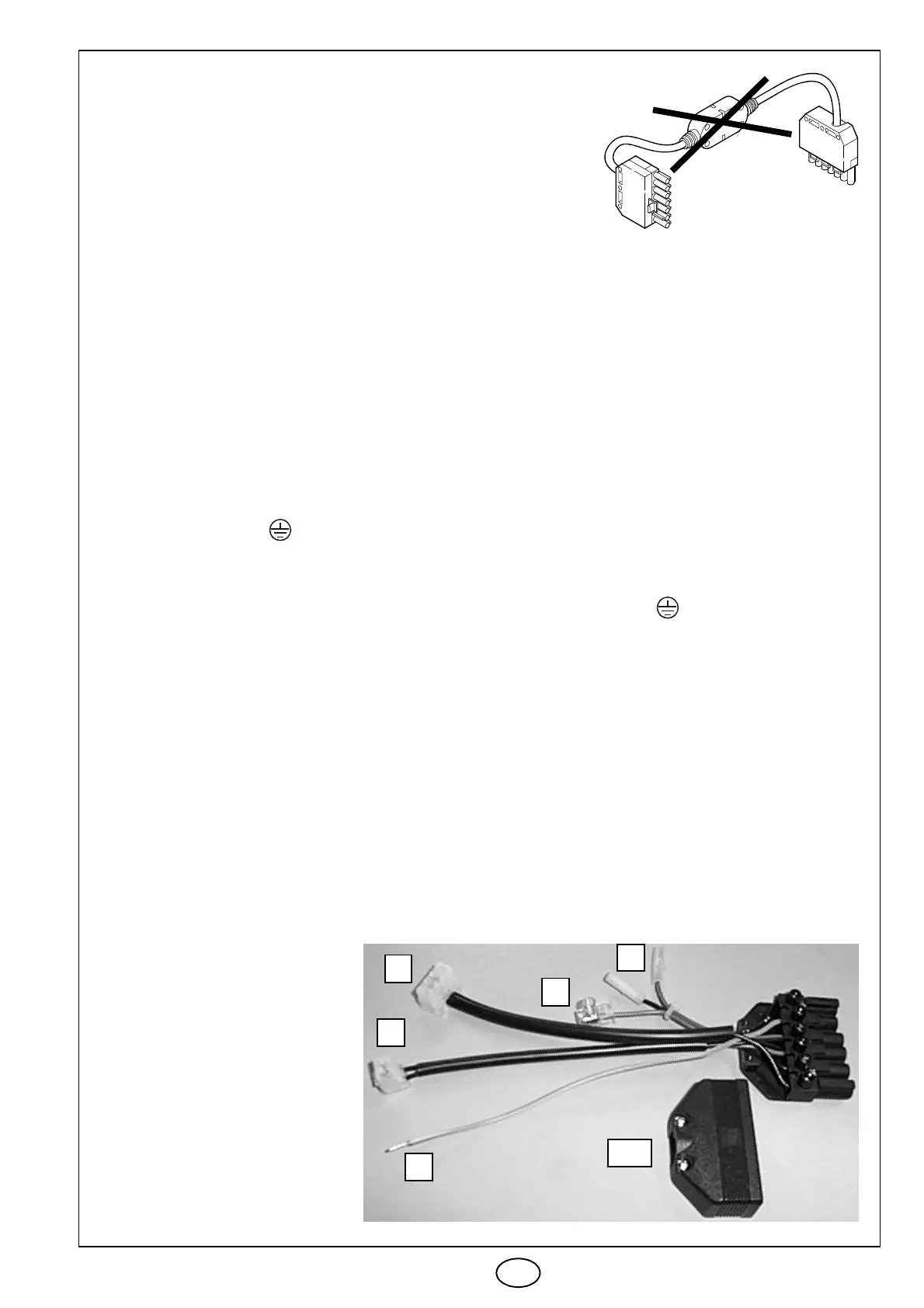
Use the assembly connection (fig. 6) as the following in-
structions.
Fig. 5
E9264
SINGLE STAGE BURNERS
Type
911T - 912T - 913T - 914T
® Disconnect the 6 pin plug of the gas train from
the 6 pole socket of the burner.
® Disconnect all the control box's connections.
® Disassemble the 6 pole socket and the respec-
tive connection.
® Disconnect control box from the burner by un-
screwing the screw (A, fig. 3, page 1) and pull in
the direction indicated by the arrow.
® Fasten the new socket (XP6), instead of the
previous one.
® Connect the yellow/green wire (D) to the earth
clamp of the burner .
®
Install the new control box, fastening it to the
burner by means of the screw (A, fig. 3, page 1)
with a driving torque of 1 to 1.2 Nm.
® Insert the four-way connector (B) in the control
box (SM-PG).
® Insert the two-way connector (A) in the control
box (V1).
® Make the rest of the connections to the control
box.
NOTE
The wires (F - G, fig. 6) are bound by a clip these
wires are useless for these burners.
TWO STAGE BURNERS
Type
915T - 916T - 917T - 918T
® Disconnect the 6 pin plug of the gas train from
the 6 pole socket of the burner.
® Disconnect all the control box's connections.
® Disassemble the 6 pole socket and the respec-
tive connection.
® Disconnect control box from the burner by un-
screwing the screw (A, fig. 3, page 1) and pull in
the direction indicated by the arrow.
® Remove the two-way connection from the control
box (V1), disconnect the blue wire (of the servo-
motor) and cut the other wire by removing the
red connector.
® Fasten the new socket (XP6), using the screws
of the previous one.
® Connect the yellow/green wire (D) to the earth
clamp of the burner .
®
Install the new control box, fastening it to the
burner by means of the screw (A, fig. 3, page 1)
with a driving torque of 1 to 1.2 Nm.
® Insert the four-way connector (B) in the control
box (SM-PG).
® Insert the two-way connector (A) in the control
box (V1).
® Connect the blue and black wires (G) with the
respective blue and black wires of the servo-
motor.
® Join the blue wire of the cable of the external 4
pole socket (XP4), with the adjustable clamp (F).
XP6
G
F
B
A
D
S7609
ATTENTION:
®
Once you have done, make
sure the burner is working
properly, checking that the
burner shuts down when the
low-limit gas pressure switch
opens and checking switching
between first and second
stage with the aid of the rele-
vant thermostat.
®
In the event of firing or opera-
tion problems, press the lock-
out reset button. This can be
repeated 3 times maximum.
Fig. 6