9
20113295
Technical description of the burner
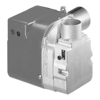
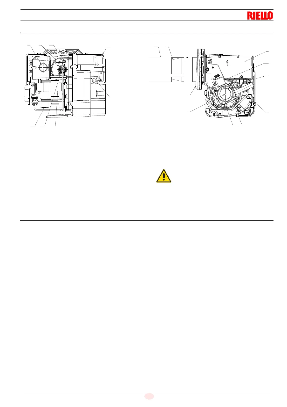
4.4 Burner description
1 Oil pump
2 Air damper adjustment screw
3 Reset button with lockout lamp
4 Flame sensor
5 Control box
6 Pump pressure adjustment screw
7 Extension for gauge connection
8 Combustion head
9 Flange with insulating gasket
10 Air inlet
11 Motor
12 Motor ignition capacitor
13 Fuel suction line
14 Return line
15 Combustion head adjustment handle knob
16 Coil
17 Air pressure test point
18 Recirculating pipe
4.5 Material supplied separately
Fitting G 3/8 (for flexible hoses) . . . . . . . . . . . . . . . . . . . . . No. 1
Screws and nuts for flange to be fixed to boiler . . . . . . . . . No. 4
Screw and nut for securing the burner to the flange. . . . . . No. 1
Hexagonal wrench . . . . . . . . . . . . . . . . . . . . . . . . . . . . . . . No. 1
Flange . . . . . . . . . . . . . . . . . . . . . . . . . . . . . . . . . . . . . . . . No. 1
Flat gasket . . . . . . . . . . . . . . . . . . . . . . . . . . . . . . . . . . . . . No. 1
Screw of by-pass pump . . . . . . . . . . . . . . . . . . . . . . . . . . . No. 1
Flexible oil pipe. . . . . . . . . . . . . . . . . . . . . . . . . . . . . . . . . . No. 1
Screw and terminal screw for feeding cable. . . . . . . . . . . . No. 3
Instruction. . . . . . . . . . . . . . . . . . . . . . . . . . . . . . . . . . . . . . No. 1
18 8
5
16
6
7
1
9
14
13
1743
11 15 12
10
2
The hoses supplied with this burner are not suita-
ble for use with light oil containing a bio blend.
In case of use with light oil containing up to 30%
bio blend, it will be essential to use flexible oil lines
suitable for biofuel use.
Please contact the manufacturer for further infor-
mation.