Electrical wiring
20113295
22
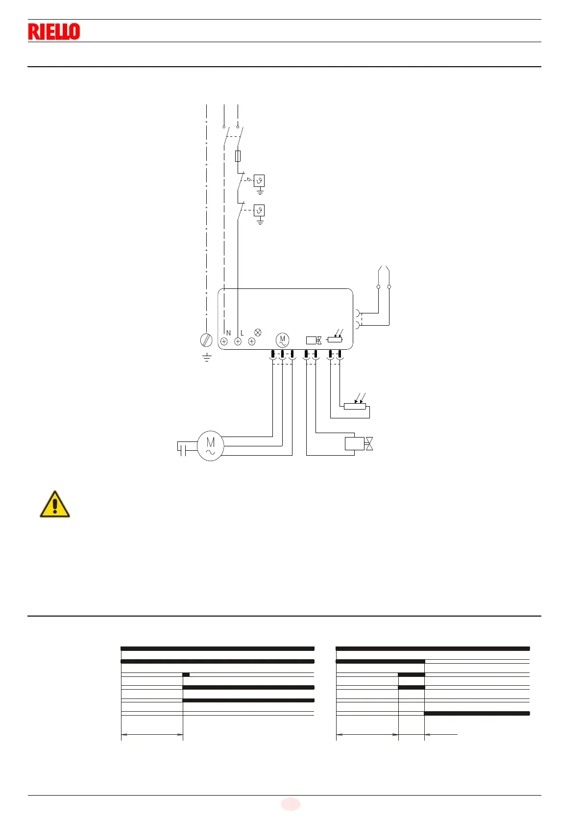
7.3 Electrical wiring diagram
TESTING:
Check the shut-down of the burner by opening the thermostats
and the lock-out by darkening the flame sensor.
7.4 Burner start-up cycle
Lock out is indicated by a lamp on the control box 3)(Fig. 1 on
page 8).
Safety thermostat
Limit thermostat
T6A
Burner-earth
Capacitor
Motor
Valve
Ignition
electrodes
N L
Main switch
PE
Blue
White
Black
Flame sensor
Do not swap neutral and phase over, follow
the diagram shown carefully and carry out a
good earth connection.
The electrical wiring carried out by the
installer must be in compliance with the rules
in force in the country.
The section of the conductors must be at
least 1mm
2
. (Unless requested otherwise by
local standards and legislation).
Fig. 23
Thermostat
Motor
Ignition transformer
Valve
Flame
Lock-out lamp
~ 12s
D5229
~ 12s
~ 5s
Lock-out due to failure to lightNormal