Technical description of the burner
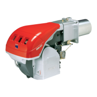
4.4 Burner dimensions
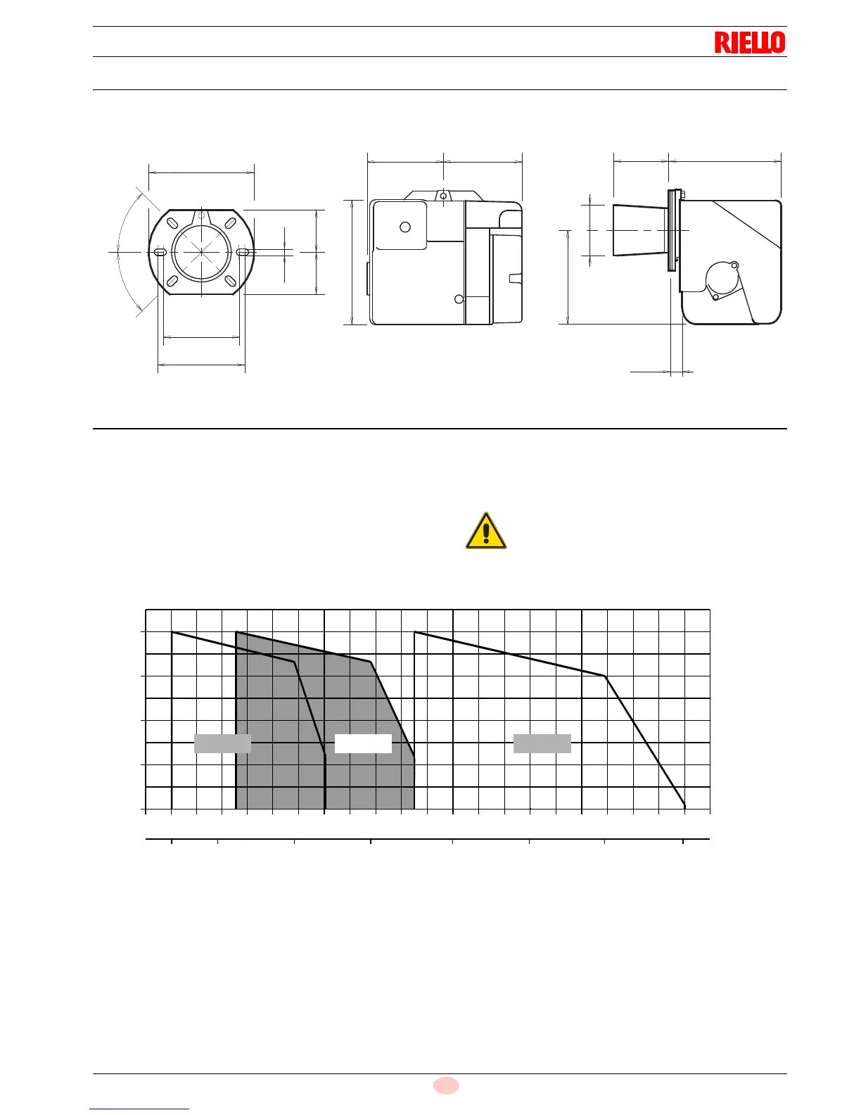
4.5 Firing rates
The MAXIMUM OUTPUT is chosen from within the diagram area
(Fig. 3).
The MINIMUM OUTPUT must not be lower than the minimum
limit of the diagram.
The burner delivery must be selected within area of the diagrams
(Fig. 3). This area is called firing rates and provides the maximum
delivery of the burner in relation to the pressure in the combustion
chamber.
The work point may be found by plotting a vertical line from the
desired delivery and a horizontal line from the pressure in the
combustion chamber. The intersection of these two lines is the
work point which must lie within the firing rates.
The firing rate area values have been obtained
considering a surrounding temperature of 20 °C,
and an atmospheric pressure of 1013 mbar (ap-
prox. 0 m above sea level) and with the combus-
tion head adjusted as shown on page 19.