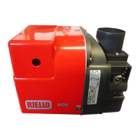
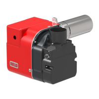
Electrical system
7.2 Electrical wiring
TESTING:
Check the shut-down of the burner by opening the thermostats
and the lock-out by darkening the photoresistance.
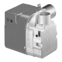
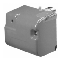
7.2.1 Control box
To remove the control box (Fig. 18) from the burner follow of the
istruction:
Loosen the screw 1), open the protection 2) and remove all
components.
Remove the coil 3).
Loosen the two screws 4).
Move a little the control box and remove the high voltage
leads.
Do not swap neutral and phase over, follow
the diagram shown carefully and carry out a
good earth connection.
The electrical wiring carried out by the
installer must be in compliance with the rules
in force in the country.
The section of the conductors must be at
least 1mm
2
. (Unless requested otherwise by
local standards and legislation).
Fig. 17
Capacitor
LN
~
50Hz - 230V
Limit
Oil valve
D4240
CONTROL BOX
Photoresistance
535SE/LD
thermostat
Safety
thermostat
Motor
Remote lock-out signal
(230V - 0.5A max.)
Main switch
T6A
Blue
White
Black
PE
Ignition
electrodes
Burner-earth
This operation must be performed with the burner
turned off and mains power disconnected.