25
20068131
Installation
Air adjustment
Rotate the screw 4)(Fig. 19) until the notch you have found cor-
responds with the front surface 5) of the flange.
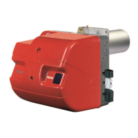
Example:
RS 44/E MZ, burner output = 300 kW.
From diagram (Fig. 18) you can see that for this output the air
should be adjusted at notch 3, subtracted from the value of the
pressure in the chamber.
Central air adjustment
In case the application needs a particular setup, it is possible to
modify the central air delivery using the ring nut 7)(Fig. 19) up to
the notch indicated in diagram (Fig. 20).
In order to carry out this operation, unscrew the screws
8)(Fig. 19) and lift up the ring nut 7).
At the end, tighten the screws 8) again.
The adjustments indicated can be modified during the initial
start-up.
5.9 Burner closing
Once the combustion head adjustment is completed:
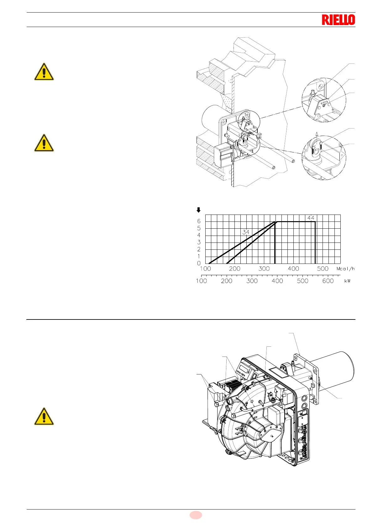
reassemble the burner on the guides 3) at about 100 mm
from the pipe coupling 4) - burner in the position shown in
Fig. 17;
insert the probe and electrode cables, then slide the burner
as far as the pipe coupling - burner in the position shown in
Fig. 21;
connect the plug of the servomotor 14)(Fig. 17) and tighten
the grommet 15);
refit the screws 2) on the guides 3);
fix the burner to the pipe coupling with the screw 1).
To facilitate the adjustment, loosen the screw
6)(Fig. 19), adjust, then block.
If the chamber pressure is equal to 0 mbar, the air
adjustment is made referring to the dotted line of
diagram (Fig. 18).
Fig. 20
No. notches
Max burner output
D8577
When fitting the burner on the two guides, it is ad-
visable to gently draw out the high voltage cable
and flame detection probe cable until they are
slightly taut.