Do you have a question about the Riello RX 180 S/PV and is the answer not in the manual?
Manufacturer, product, standards, and CE marking details.
Producer, measured values, and controlling organization.
Compliance with German NOx emission limits.
Needs specific values for low emissions.
Professional and technical requirements for personnel.
LED signal and rearming procedure for safety stop.
Prohibitions for children, covering vents, repairs, etc.
Integral part of the product, intended for qualified personnel.
Manual placement and user information on delivery.
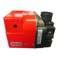
RX 180/250 S/PV models and output ranges.
Natural Gas G20-G31 properties and data.
Supply, motor, ignition, power consumption, and protection.
Country-specific categories and optional kits.
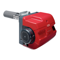
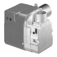
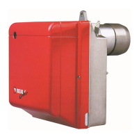
Labeled parts diagram and list of burner components.
Control box lockout and reset procedure.
Box sizes, weight, and burner dimensions.
List of parts and accessories supplied with the burner.
Specifies the operational output ranges for the burner.
Guidance on choosing firing power based on gas type.
Notes on firing rate settings related to test boilers.
Advice for combining with non-CE approved boilers.
How to read motor RPM or gas valve pressure.
Step-by-step guide for determining output.
Conformance to local legislation and standards.
Allowed and forbidden orientations for burner installation.
Modifying boiler plate and selecting head length.
Prohibition of use on specific boiler types.
Guidance on using refractory material in the combustion head.
Securing the combustion head and electrode unit.
Connecting high voltage and probe leads.
Attaching the gas train and mounting the flange.
Description of proportioning gas valves.
Explanation of how the air/gas mixer works.
Details of the gas train system and its approval.
Opening valves and bleeding air before firing.
Step-by-step ignition process and fault resolution.
Adjusting fan speed for output modulation.
Adjusting maximum and minimum gas flow.
Using analyzers to set CO2/O2 levels.
Adjusting control box trimmers for output.
Optimal CO2/O2 for Methane and LPG.
Heat resistance, mesh, and flame retention.
Low emissions compared to EN 676 standards.
How flame design limits thermal NOx.
Electrical, gas leak, and combustion head checks.
Inspecting electrodes and gas train components.
Service by a qualified technician.
Power off and gas shutoff procedures.
Checking and adjusting combustion values.
Potentiometer settings and limits.
List and explanation of error codes.
Sequence of burner operation steps.
Table of safety settings with min/max values.
Description of the BCC for parameter updates.
Visual representation of the burner start-up sequence.
Visual representation of the burner shut down sequence.
Wiring schematic for the CM222 control box.
Identification of connection points on the control unit.
Important electrical connection guidelines and compliance.
Socket details for RX 180 S/PV and RX 250 S/PV.
Using power regulators and converters for modulation.
Minimum current requirements and measurement.
Detailed wiring of the CM222 control box.
Wiring for fan, ignition, valves, and other components.
Key to wire colors used in the diagrams.
Connections for the fan power module.
Connections for the gas valves.
Diagram for connecting the remote reset button.
Wiring for external modulation and setpoint signals.
Connecting various probe types in different circuits.
Connecting probes with standard current/voltage outputs.
Specific wiring for the QBE620-P modulation input.
Wiring for climatic compensation and setpoint shift.
Italian/French explanations of electrical components.
English explanations of electrical components.
| Air Regulation | Mechanical |
|---|---|
| Protection Degree | IP40 |
| Electrical Supply | 230V |
| Stages | Single stage |
| Control System | Electronic |
| Voltage | 230V |
| Frequency | 50 Hz |