Do you have a question about the Riello VOKERA Easi-Heat Plus Ci and is the answer not in the manual?
Essential information before operating the boiler, covering gas, electrical, and guarantee details.
Legal requirement for gas appliance installation and maintenance by competent persons.
Guidance on proper connection to the electrical supply, including fuse rating and earthing.
Instruction to fill out and post the guarantee registration card within 30 days of installation.
Importance of the commissioning checklist and how to verify installer credentials via GAS SAFE.
Explanation of the boiler's operation for heating and hot water, including ignition and safety features.
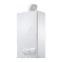
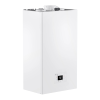
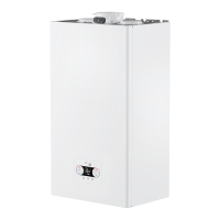
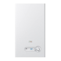
Provides the physical dimensions of the Easi-Heat Plus 25-29-32 Ci boiler.
Specifies minimum clearance distances required around the appliance for installation.
Details the built-in frost protection system and its operational parameters.
Explains the function of the Green, Red, and Yellow status LED indicators on the boiler.
Initial steps and checks required before operating the boiler for the first time.
Pre-operation checks and familiarisation with appliance controls and supplies.
Identifies and describes the main controls located on the lower front of the appliance.
Instructions for ensuring gas and electrical supply are on before lighting the boiler.
Practical guides for common user tasks and troubleshooting scenarios.
Step-by-step guide to checking and topping up the heating system water pressure.
Procedure for manually resetting the appliance when the red fault LED is illuminated.
Method for shutting down the system for brief periods using the mode selector switch.
Guidance on draining the system and turning off supplies for extended periods.
Instructions for cleaning the appliance outer casing using a damp cloth.
Table detailing fault causes, alarm codes, LED indications, and alarm types.
Troubleshooting guide addressing common user concerns and potential issues.
Actions to take if a gas leak is suspected, including contacting the gas supplier.
Advice to contact an installer if the system frequently requires topping up, indicating a potential leak.
Guidance for tenants and homeowners on arranging annual servicing for the appliance.
Information on what details to provide when calling an engineer for a boiler fault.
Lists the key integrated electronic and mechanical components of the boiler.
Describes functions active when the appliance is idle, including frost protection.
Explains the boiler's operation sequence when a heating request is received.
Details the boiler's operation sequence when a hot water request is made.
Lists the various safety devices incorporated into the appliance to ensure safe operation.
Provides technical specifications for the central heating output and performance.
Lists technical specifications related to the domestic hot water performance.
Details the required gas pressures for natural gas operation.
Specifies the fan speeds for ignition and heating/DHW modes.
Provides information on the boiler's expansion vessel capacity and pre-charge pressure.
Lists the physical dimensions of the boiler models.
Specifies minimum installation clearance requirements.
Details the types and sizes of connections for various services.
Provides electrical consumption and fuse rating details.
Specifies flue lengths and types for horizontal and vertical installations.
Lists energy efficiency ratings and SEDBUK values.
Details the emissions output, including CO2 and NOx ratings.
Presents a graph showing pump flow rate against residual head for system requirements.
Lists relevant British Standards and regulations for boiler installation.
Specifies requirements for the appliance's installation location, especially regarding baths/showers.
Details requirements for the gas supply, meter size, and pipework integrity.
Provides guidance on flue terminal location and consideration of pluming effects.
Notes that the room-sealed, fan-flued boiler does not require a permanent air vent.
Refers to recommendations for water circulation systems and pipework insulation.
Specifies the appliance's electrical supply requirements, fuse, and isolation methods.
States no specific wall protection is required for mounting on combustible material.
Refers to specific guidance for installations in timber-framed buildings.
Recommends water treatment in accordance with Benchmark Guidance, suitable for aluminium heat exchangers.
Guidance for using the appliance with a shower, recommending a thermostatic control.
Advice on handling the appliance during delivery, possibly requiring two people.
Lists the items included within the appliance carton.
Instructions for safely unpacking the appliance and its accessories.
Guidance on preparing the mounting surface and marking for bracket and flue hole.
Instructions for fitting the flue system, including concentric horizontal and vertical types.
Specific instructions for installing the concentric horizontal flue system.
Guidance for installing the concentric vertical flue system and its components.
Instructions for connecting the gas, flow/return, cold water, and hot water services.
Details on connecting the gas supply pipe to the appliance's service valve.
Instructions for connecting the central heating flow and return pipes.
Guidance on connecting the cold water inlet pipe with a stopcock.
Instructions for connecting the hot water outlet pipe.
Guidance for connecting the safety valve discharge pipe to a visible location.
Recommendations for connecting and routing the condensate disposal pipework.
Instructions for connecting the flexible condensate outlet pipe to the trap.
Details on connecting the appliance to the electrical supply and internal wiring.
Step-by-step guide on how to remove the appliance casing for access.
Location of the appliance terminal block on the control fascia.
Instructions for connecting the 230V mains input supply to the terminal block.
Checks for gas supply installation, tightness, and purging as per regulations.
Importance of flushing the heating system to remove debris before operation.
Procedure for filling the condensate siphon with water before initial use or after maintenance.
Steps for filling the heating system, venting air, and setting initial pressure.
Guidance on flushing the entire heating system both cold and hot before operation.
A checklist of essential checks to perform before attempting to light the appliance.
Instructions for switching on the appliance and initiating the ignition sequence.
Procedures for checking gas pressures and performing combustion analysis as per standards.
Guidance on final flushing of the system, including the use of approved cleansers.
How to adjust the central heating flow outlet temperature using the thermostat knob.
How to adjust the domestic hot water outlet temperature using the thermostat knob.
Guidance on setting the correct system design pressure for safe operation.
Instructions for balancing radiator return temperatures and branch circuit returns.
A list of final checks to ensure system integrity and security before completion.
How to explain appliance operation, isolation, and maintenance to the user.
Importance of completing the Benchmark Service Record and using genuine spare parts.
Steps for performing routine annual servicing, including checks and adjustments.
Guidance on identifying faulty components and their replacement procedures.
General steps for accessing and removing internal appliance components safely.
Procedure for removing and replacing the pump assembly.
Procedure for removing and replacing the safety valve.
Procedure for removing and replacing the main printed circuit board.
Procedure for removing and replacing the gas valve unit, including sealing washers.
Procedure for removing and replacing the burner assembly.
Procedure for removing and replacing the main heat exchanger.
Procedure for removing and cleaning the condense trap and siphon.
Procedure for removing and replacing the flue collector.
Importance of ensuring continued safe operation after repairs, checking gas/water tightness.
Details the different operational modes: OFF/RESET, on-board functions, heating, and DHW.
Procedures for checking CO2 levels and adjusting the gas valve using a flue gas analyser.
How to perform a combustion analysis test using test points on the appliance.
Procedure to check the charge pressure of the expansion vessel.
Advice to check installation aspects before faultfinding on the appliance itself.
Procedures for performing electrical checks including earth continuity, short circuit, and polarity.
Steps to follow for fault finding, including disconnecting external controls and checking fuses.
A table listing key component values and characteristics for reference.
Shows diagrams for connecting external controls to the appliance.
Lists typical voltage-free controls compatible with the appliance.
Wiring diagram for connecting an external room thermostat in series with the integral clock.
Wiring diagram for connecting a 1-channel external time clock.
Wiring diagram for connecting an external programmable room thermostat.
Lists relevant standards and regulations for LPG installations.
Provides technical data specific to LPG operation of the appliance.
Instructions for converting the appliance from natural gas to LPG, including injector and gas valve adjustments.
Requirements for connecting the LPG gas supply, ensuring adequate size and tightness.
Steps for installing and purging the LPG gas supply system.
Procedure for checking CO2 and adjusting the gas valve for LPG, using a flue gas analyser.
Condition for warranty eligibility regarding installation by a registered Gas Safe installer.
Requirement for annual servicing by a Gas Safe Registered Engineer to maintain warranty.
Health and safety considerations for engineers attending boiler issues, including access and clearances.
Lists circumstances and defects that are excluded from the warranty coverage.
Information on how Vokèra collects, uses, and protects customer personal data.
Contact details for Vokèra's Customer Care Centre for service and support.