RIGOL Chapter 2 Performance Verification Test
DSA1000A/DSA1000 Performance Verification Guide
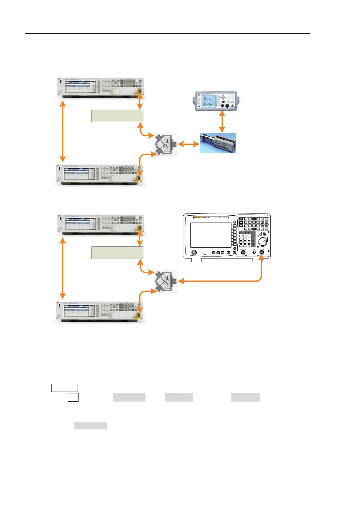
Test Connection Diagram
Signal Generator B
Signal Generator A
Low Pass Filter
(a
)
(
b)
REF IN
10MHz OUT
Dual-BNC Cable
RF OUT
RF OUT
Dual-N Cable
N-SMA Cable
Power Divider
Power Meter
Power Sensor
Power Meter
Connecting Cable
Signal Generator B
Signal Generator A
Low Pass Filter
REF IN
10MHz OUT
Dual-BNC Cable
RF OUT
RF OUT
Dual-N Cable
N-SMA Cable
Power Divider
Dual-N cable
DSA1030A
RF IN
N-SMA Cable
N-
SMA Cable
Figure 2-6 TOI Distortion Test Connection Diagram
Test Procedures
1. Calibrate the power meter:
a) Connect the power sensor with the [REF] terminal and channel A of the power meter. Press
Channel and set the frequency of channel A to 50 MHz.
b) Press Cal and enable Power Ref in the Zero/Cal menu. Press Zero+Cal and wait for the
calibration to finish; then, observe whether the measurement value of the power meter is a
0 dBm, 50 MHz signal.
c) Disable Power Ref.
2. Synchronize the two signal generators.
Set the output frequency of signal generator A to 1 GHz and the amplitude to -10 dBm.
 Loading...