EasyManua.ls Logo

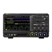
Rigol MSO5354 User Manual

Rigol MSO5354
372 pages
To Next Page IconTo Next Page
Page #1 background imageLoading...
Page #1 background image
User Guide
MSO5000 Series Digital
Oscilloscope
May. 2020
RIGOL TECHNOLOGIES CO., LTD.

Table of Contents

Other manuals for Rigol MSO5354

Questions and Answers:

Rigol MSO5354 Specifications

General IconGeneral
BrandRigol
ModelMSO5354
CategoryTest Equipment
LanguageEnglish

Summary

Safety Requirement

General Safety Summary

Essential safety precautions for operating the oscilloscope to prevent personal injury or instrument damage.

Safety Notices and Symbols

Explanation of warning symbols and terms used for safety in the manual and on the product.

Measurement Category

Ventilation Requirement

Specifies clearance and airflow needs for proper cooling and instrument longevity.

MSO5000 Series Overview

Main Features

Highlights key specifications and capabilities of the MSO5000 series oscilloscopes.

Chapter 1 Quick Start

Front Panel Overview

Detailed description and labeling of all front panel controls and connectors.

Rear Panel Overview

Detailed description and labeling of all rear panel connectors and interfaces.

User Interface

Explanation of the oscilloscope's graphical user interface and its elements.

Chapter 2 To Set the Vertical System

To Adjust the Vertical Scale

Adjusting the vertical scale (V/div) for controlling waveform amplitude display.

Chapter 3 To Set the Horizontal System

To Adjust the Horizontal Time Base

Setting the time per division (s/div) for controlling the horizontal display of waveforms.

Chapter 4 To Set the Sample System

Acquisition Mode

Choosing modes like Normal, Average, Peak, High Resolution for data acquisition.

Chapter 5 To Trigger the Oscilloscope

Trigger Source

Selecting the signal source (analog, digital, AC line) for triggering the acquisition.

Trigger LEVEL/Threshold Level

Adjusting the voltage level for triggering based on signal type and edge.

Trigger Mode

Selecting between Auto, Normal, or Single trigger modes for acquisition behavior.

Trigger Type

Choosing from various trigger types like Edge, Pulse, Slope, Video, Pattern, etc.

Chapter 6 Operations and Measurements

Math Operation

Performing arithmetic, logic, FFT, and filter operations on waveforms.

Auto Measurement

Automatically measuring waveform parameters like period, frequency, rise time.

Cursor Measurement

Using cursors to measure X (time) and Y (voltage) values on waveforms.

Chapter 7 Digital Voltmeter (DVM) and Frequency Counter

Chapter 8 Power Analysis (Option)

Power Quality

Testing the quality of AC input lines with various parameters like RMS, power factor.

Chapter 10 Digital Channel

Chapter 11 Protocol Decoding

Chapter 13 Pass/Fail Test

To Enable or Disable the Pass/Fail Test Function

Activating or deactivating the pass/fail test function for product testing.

To Create a Mask

Defining custom masks for pass/fail criteria based on waveform regions.

Chapter 14 Waveform Recording & Playing

Waveform Recording

Capturing and storing waveforms from analog and digital channels at specified intervals.

Chapter 15 Search and Navigation Function

Chapter 17 Function/Arbitrary Waveform Generator (Option)

To Output Basic Waveforms

Generating standard waveforms like Sine, Square, Ramp, Pulse, DC, Noise.

Chapter 18 Store and Load

Chapter 19 Bode Plot

To Enable the Bode Function

Activating the Bode plot analysis for frequency response measurement.

Chapter 20 System Utility Function Setting

Remote Interface Configuration

Setting up USB, LAN, or GPIB interfaces for remote control and communication.

Chapter 21 Remote Control

User-defined programming

Controlling the oscilloscope remotely using SCPI commands for custom automation.

PC software

Using PC software like RIGOL Ultra Sigma for remote control and data acquisition.

Remote Control via USB

Connecting and controlling the oscilloscope remotely via the USB interface.

Remote Control via LAN

Connecting and controlling the oscilloscope remotely via the LAN interface.

Chapter 22 Troubleshooting

Power and Display Issues

Solutions for the instrument not powering on or displaying anything.