B
brianna51Aug 9, 2025
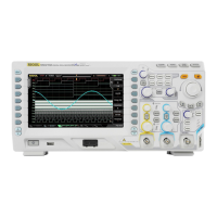
What to do if Rigol MSO5104 Test Equipment stays black after power on?
- DDarlene JordanAug 9, 2025
If your Rigol Test Equipment's screen remains black after powering it on, verify that the power switch is turned on and the power cord is correctly connected. Also, check the fuse and replace it if necessary with the specified type. After these checks, restart the equipment. If the issue continues, it may require professional assistance.