- 4 -
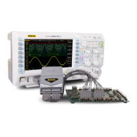
2. Connect the signals under test to RPL1116: users can connect
any number (≤16) of the signals under test to RPL1116 according to
the test requirements. Note that the amplitude of the input signal
should not exceed the maximum working voltage range of the probe.
RPL1116 provides two connection methods to realize convenient and
flexible detection.
Method 1: users can connect the signals under test through the
probe leads separately. You can easily identify the
corresponding channel of each signal by the channel label on
the probe leads and the color information on the probe head as
shown in Figure 1.
Note: The crosstalk or ground bounce during use may be
caused by the fact that the channels share a single ground lead.
Therefore, you are recommended to add one ground wire to the
signal lines of each channel and twist them.
Method 2: on the basis of Method 1, you can connect a grabber
to each lead and connect it to the device under test as shown in

 Loading...