25
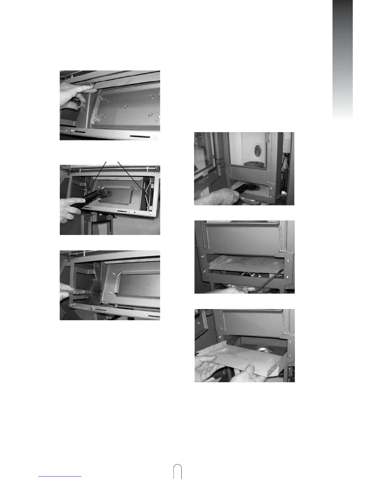
➧ Clean the inserted intermediate floor
(Fig. 5, Part 33) (e.g. with vacuum cleaner)
and then remove from combustion
chamber
➧ Now vacuum the combustion residue
from the manifold channel.
➧ Fit the parts in the reverse order again.
Attention must be paid to a tight fit.
Fig 5
Cleaning the flues
Fig 7
➧ Refit the parts you removed in the
reverse order.
Fig 4
Fig 6
CLEANING THE FLUE MANIFOLD
The heating flue is located in the bottom of
the combustion chamber (Fig. 7 to Fig. 10)
➧ After removing the front panels (see
page 15, remove cast cover and
dismantle front panel, Fig. 6, 47)
➧ Open the grate door
➧ Dismantle the bottom inspection
opening Fig. 5, 33 (four wing nuts)
Fig 8
Fig 9
ENGLISH