5
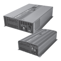
Fig3 – Integral RCD example
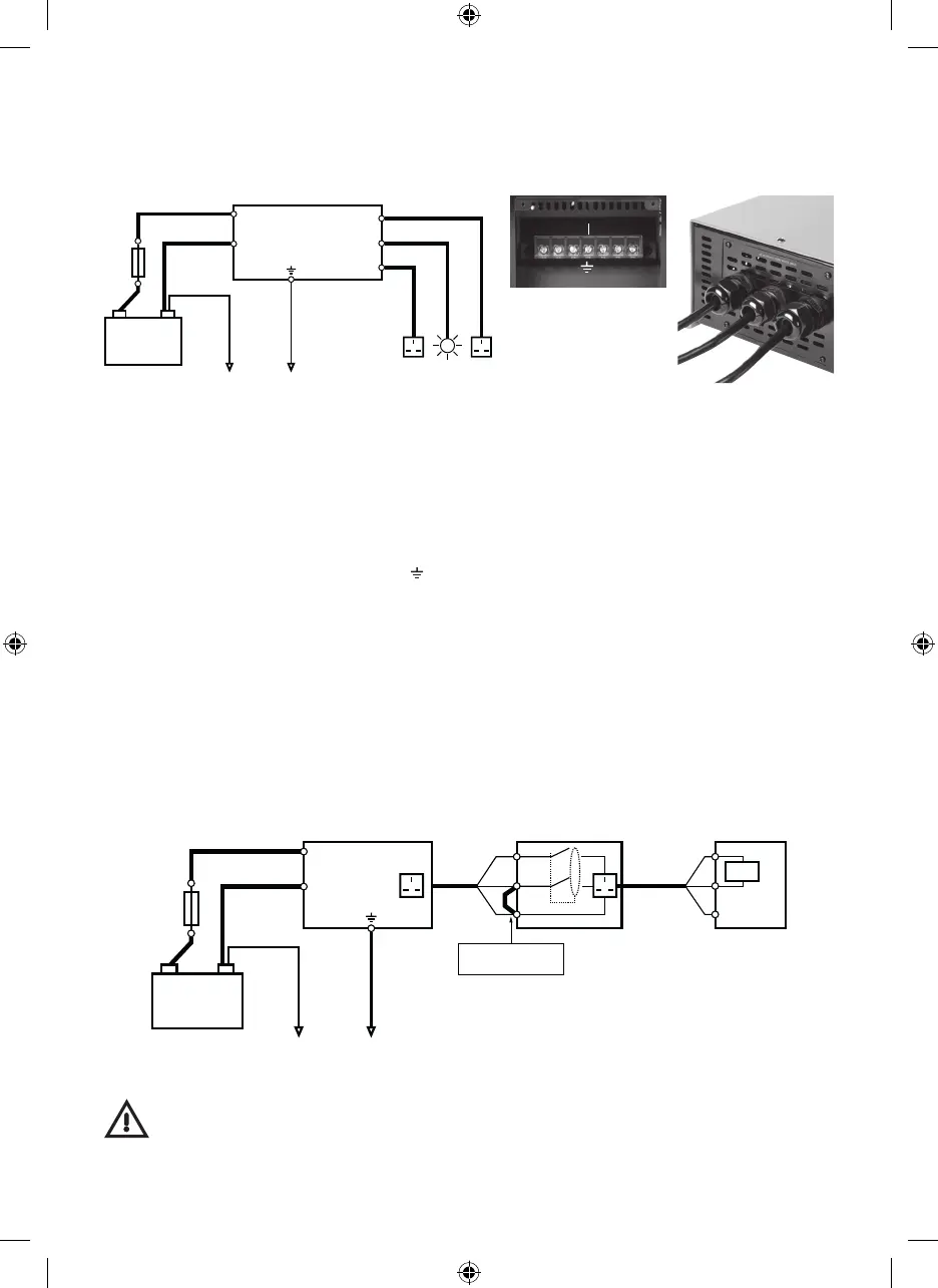
Fig5 – External RCD example
Fig4 – AC terminals Fig5 – Gland fitment
Caution
It is recommended the inverter is wired and tested by a qualified electrician
AC Output Connections - Models with integral RCD
To make installation simpler and provide a more integrated solution, some models are provided with internal
RCD protection and screw terminal connections. Fig3 below shows an example installation
AC Output Connections - models without integral RCD
An RCD device can still be used on models without this feature integrated into the inverter. The diagram
below shows recommended wiring for 230V sockets with an integral RCD. Note:- In order for an RCD device
to trip effectively when used in a vehicle, the neutral output from the inverter should be linked to the
earthing system of the installation. Fig5 below shows a recommended installation
1. Remove 4 x screws from cover plate to allow access to terminals
2. Knockout the required number of apertures and fit supplied cable glands
Outer glands are suitable for up to 2.5mm
2
3-core cable
Central gland is suitable for up to 1.5mm
2
3-core cable
3. Pass cables through gland assemblies then attach to 230V output terminals (see Fig4)
Live(L) = Brown, Neutral(N) = Blue, Earth(
) = Green/Yellow
Note:- It is recommended the supplied fork terminals are used for a more secure connection
4. Re-fit cover plate, fully tighten glands and check cables cannot move (see Fig5)
Inverter
Battery
Inverter
+
–
–
Vehicle
Chassis
Example outputs
Output 1
Output 2
Output 3
230V AC
F1
Inverter
Battery
Inverter
+
+
–
–
Vehicle
Chassis
Appliance230V Socket with integral RCD
Fit N-E link to ensure
RCD will trip
L
N
E
L
N
LOAD
E
F1
Earth
230V AC
Output1
{
{
{
LIVE
LIVE
LIVE
NEUTRAL
NEUTRAL
NEUTRAL
230V AC
Output2
230V AC
Output3
L1 L3N1 N2 N3L2
8pp A5 (PSW) UK Full Handbook v4.indd 5 07/04/2014 09:48