Do you have a question about the Rinnai 650 and is the answer not in the manual?
Heater requires installation by an authorised person per local regulations.
Rinnai Gas Fires are certified by the Australian Gas Association.
Lists components supplied in separate cartons for installation purposes.
Fields for installer name, company, address, and contact information.
Fields for appliance model, serial number, and installation address.
Covers fire/explosion risks, authorised personnel, flue requirements, combustibles, and safe usage.
Details prohibited actions and placements for the heater, including user interaction.
Covers electrical safety, component care, and initial operation behaviour and warnings.
Details the function and operation of various safety devices integrated into the heater.
Overview of the natural draft system, burner, and heat output control mechanisms.
Describes the two main installation configurations: Masonry and Zero Clearance installations.
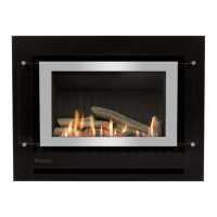
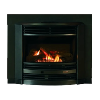
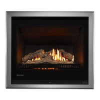
Identifies key heater components and controls, including panel and remote features.
Step-by-step guide for turning the heater on via the control panel.
Instructions for turning the heater off using the control panel.
Explains safety feature and restart procedure following electricity or gas supply interruptions.
Describes limited operation via control panel versus full operation via remote control.
Safety precautions for button batteries and steps to activate the remote control unit.
Step-by-step guide for replacing CR2450 button batteries in the remote control.
Instructions for operating the appliance if the remote control is lost or broken.
Guidelines for safely and effectively cleaning the heater unit.
Recommendations for periodic servicing and contact information for repairs.
Explanation of error codes displayed by the heater and corresponding suggested remedies.
Chart to determine if a service call is required based on observed fault symptoms.
Identifies abnormal flame patterns and key signs indicating potential problems.
Safety precautions and recommendations for the use of CR2450 batteries.
Table of normal operating noises and characteristics that do not indicate a fault.
Technical specifications including model, features, input, output, efficiency, and heating area.
Table detailing external dimensions and flue centre measurements for various models.
Guidance on heater positioning, considering flueing and warm air distribution factors.
Warnings regarding installation of TVs or ornaments above the heater unit.
Requirements for installing the appliance within a masonry fireplace enclosure.
Installation framework and requirements specific to false fireplace setups.
Detailed enclosure dimensions for Masonry, False Fireplace, and Corner installation types.
Information on gas pipe sizing, gas type confirmation, and consumer piping installation procedures.
Procedure for purging gas supply to prevent damage to the gas control valve.
Instructions for leak testing gas connections using a soapy solution.
Requirements for power point connection or direct wiring installation.
Illustrates flue installation options and required components for space heaters.
Details on RDVFF and RDVFA flue kits and associated components.
Describes the RDVFF (Masonry) and RDVFA (False Fireplace) basic flue kits.
Lists and describes various additional flue components along with their order codes.
Diagrams and restrictions for various flue installation types, including length requirements.
Minimum clearances required for fan-assisted flue terminals and building openings.
Steps for site preparation, unpacking, and flue installation for masonry fireplaces.
Steps for positioning, electrical connection, gas preparation, insertion, and securing of the heater engine.
Steps for site preparation, unpacking, and flue installation for false fireplaces.
Installation of the zero clearance frame, including its purpose and assembly.
Instructions for installing cladding around the zero clearance frame.
Steps for positioning, electrical connection, gas preparation, insertion, and securing the heater engine.
Procedure for connecting the flexible S/S pipe to the gas control valve.
How to test gas connections for leaks using a soapy solution.
Step-by-step guide for installing ceramic log sets, including burner inspection.
Instructions for placing charcoal bed materials and installing ceramic logs.
Steps for installing ceramic stone sets, including media placement and glass replacement.
Unpacking the fascia and connecting the control panel to the heater engine.
Connecting the fascia push button control panel via RJ45 plug and communication cable.
Connecting the appliance electrical power for commissioning purposes.
Checking gas type, pressures, and settings according to commissioning instructions.
Procedure for checking and recording supply pressures for Natural and Propane gas.
Procedure for checking and setting main burner gas pressure for different stages.
Procedure for checking and setting pilot burner gas pressure.
Re-commissioning steps for changing the appliance's gas type (e.g., NG to Propane).
Step-by-step guide for attaching the fascia assembly to the heater engine.
Checks, warnings, and advice for final installation and initial operation burn-in period.
Identifies abnormal flame patterns and key signs indicating potential problems.
Checklist for certified installers to verify installation and ensure customer understanding.
| Brand | Rinnai |
|---|---|
| Model | 650 |
| Category | Indoor Fireplace |
| Language | English |