Rinnai Water Heater Service Manual 16 100000098 Rev B
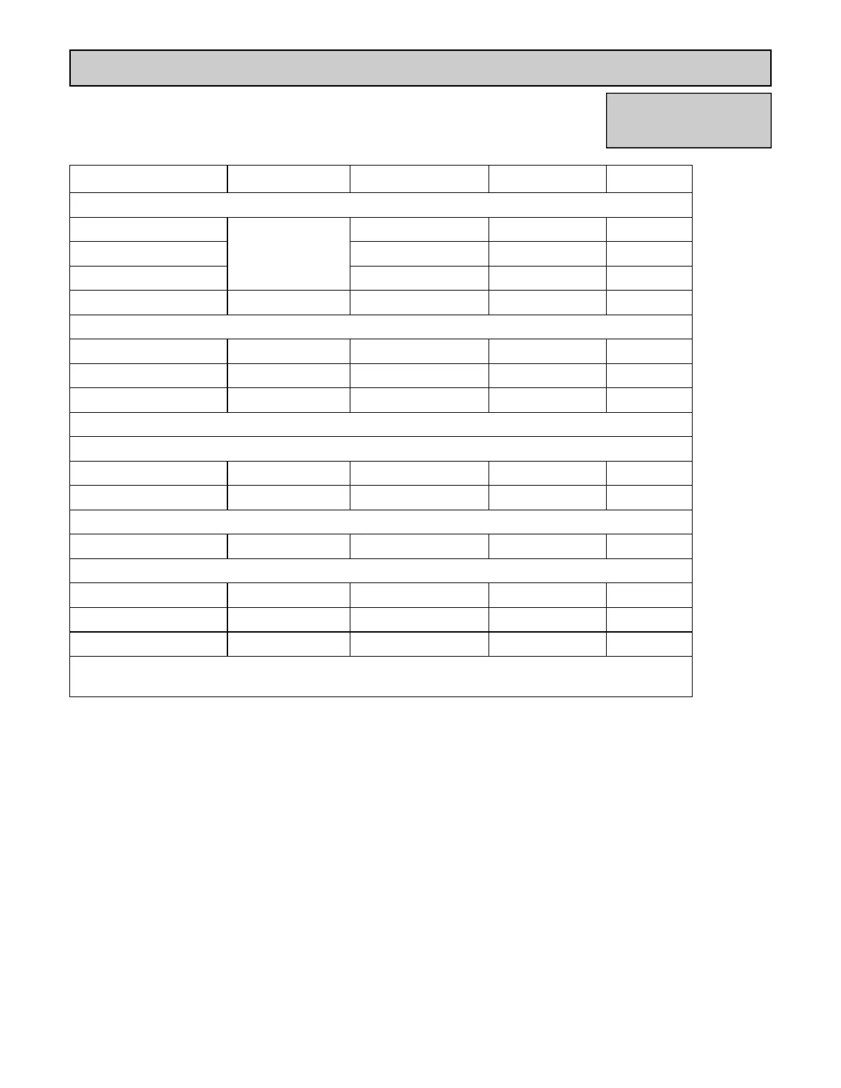
Electrical Diagnostic Points
V53e, R63LSe
Wire Color Voltage Resistance Connector No. Pin No.’s
(SV1, SV2, SV3, POV) Gas Valve and Modulating Solenoids
(Main) Pink - Black
11 - 13 VDC
37 - 43 ohms F5 1 ~ 2
(SV1) Black - Blue 35 - 41 ohms F6 1 ~ 2
(SV2) Black - Yellow 37 - 43 ohms F7 1 ~ 2
(POV) Pink - Pink 2 - 15 VDC 67 - 81 ohms F3 1 ~ 2
(M) Water Flow Servo
Red - Blue 11 - 13 VDC 22 - 28 ohms E5 (1, 2) 9 ~ 8 (E)
Gray - Brown 4 - 6 VDC N/A E5 (5, 3) 4 ~ 6 (E)
Gray - Yellow N/A N/A E5 (5, 4) 4 ~ 7 (E)
NOTE: At the E connector on the PCB: gray wire turns to black
(QS) Water Flow Sensor
Black - Red 11 - 13 VDC 5.5 - 6.2 K ohms E2 3 ~ 1
Yellow - Black 4 - 7 VDC 1 - 1.4 mega ohms E2 2 ~ 3
(IG) Ignition System
Gray - Gray 90 - 110 VAC N/A B1 1 ~ 2
(FM) Combustion Fan Motor
Red - Black 6 - 45 VDC N/A D1 1 ~ 2
White - Black 5 - 10 VDC 9.2 - 9.4 K ohms D1 4 ~ 2
Yellow - Black 11 ~ 13 VDC 3.5 - 3.9 K ohms D1 3 ~ 2
With the meter set on hertz scale, 60-420 hertz should be across the white and black wires at
terminals 2 and 4.