Do you have a question about the Rinnai Continuum Series and is the answer not in the manual?
Monitors combustion process via flame rod and compares signals for safety.
Shuts off gas supply if heat exchanger temperature reaches 194°F.
Ceases gas flow if water flow sensor fails to send magnetic pulse signal.
Breaks circuit and shuts off power if heat exchanger burns out or exceeds 264°F.
Activates anti-frost heaters to prevent freezing below 37°F.
Automatically shuts off burner if output water temperature exceeds pre-set by 5°F.
Checks vent components, blockages, and Rinnai venting materials.
Verifies gas supply, type, pressure, and igniter operation.
Inspects flame rod, gas lines, and solenoid valves for proper function.
Checks manifold gas pressure, heat exchanger integrity, and safety circuit.
Examines airflow, circulating systems, and foreign materials in exhaust.
Checks sensor wiring, resistance, and cleans scale from the sensor.
Verifies sensor wiring, resistance, and cleans scale from the sensor.
Checks sensor wiring, resistance, and fan motor condition.
Inspects solenoid valve wiring, resistance, and fan motor operation.
Checks fan motor wiring, resistance, and connection integrity.
Examines solenoid valve wiring, connections, and resistance.
Checks microamps from flame rod, carbon buildup, and wiring.
Inspects and measures resistance of the 3-amp glass fuse.
Measures voltage and resistance at the main transformer.
Measures voltage and resistance at the sensor and PCB connector.
Measures resistance and checks for carbon buildup or loose attachment.
Measures motor voltage, fan rotation sensor voltage, and speed.
Checks voltage at the sparker and resistance between its terminals.
Measures resistance and voltage at the main gas solenoid valve.
Checks resistance and voltage at the change over solenoid valve.
Measures resistance and voltage at the change over solenoid valve.
Checks resistance and voltage at the change over solenoid valve.
Measures resistance of thermal fuses and checks bi-metal switch.
Measures thermistor resistance against temperature charts.
| Type | Tankless |
|---|---|
| Fuel Type | Natural Gas or Propane |
| Maximum Water Pressure | 150 PSI |
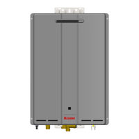
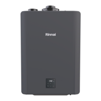
| Installation | Indoor or Outdoor |
| Maximum BTU Input | 199, 000 BTU/hr |
| Electrical Requirements | 120V |
| Warranty | 5 years parts, 1 year labor |