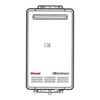
REU-2532FFU Series 41 Rinnai
6) Is the main gas solenoid valve (SV0) operating normally ?
If error “11” or “71” is displayed, check the main
gas solenoid valve.
a. # Disconnect the main gas solenoid valve (SV0)
connector and measure the resistance at the
solenoid terminals.
Normal: 1.7 ~ 2.1 KΩ
If normal, check b below.
Faulty: Replace the main gas solenoid valve.
b. Measure voltage at the main gas solenoid (SV0)
Pink and black wires.
Normal: 80 ~ 100 VDC
If normal, proceed to check item 7 below.
Faulty: Replace PCB unit.
7) Is the change over solenoid (SV1) operating normally ?
If error “11” or “71” is displayed, check the change
over solenoid (SV1).
a. # Disconnect the change over solenoid (SV1)
connector, and measure resistance at the
solenoid terminals.
Normal: 1.7 ~ 2.1 KΩ
If normal, check b below.
Faulty: Replace the change over solenoid (SV1).
b. Measure voltage at the change over solenoid
(SV1) yellow ~ black wires.
Normal: 80 ~ 100 VDC
If normal, check 8 below.
Faulty: Replace PCB unit.
8) Is the change over solenoid (SV2) operating normally?
If error “11” or “71” is displayed, check the change
over solenoid (SV2).
a. # Disconnect the changeover solenoid (SV2)
connector, and measure the resistance at the
solenoid terminals.
Normal: 1.7 – 2.1 KΩ
If normal, check b below.
Faulty: Replace the changeover solenoid (SV2).
b. Measure the voltage at the changeover solenoid
(SV2), blue – black wires.
Normal: 80 – 100 VDC
If normal, check 9, on next page.
Faulty: Replace the PCB unit.

 Loading...