REU-2532FFU Series 45 Rinnai
3) Is the modulating valve operating normally ? Error code 52
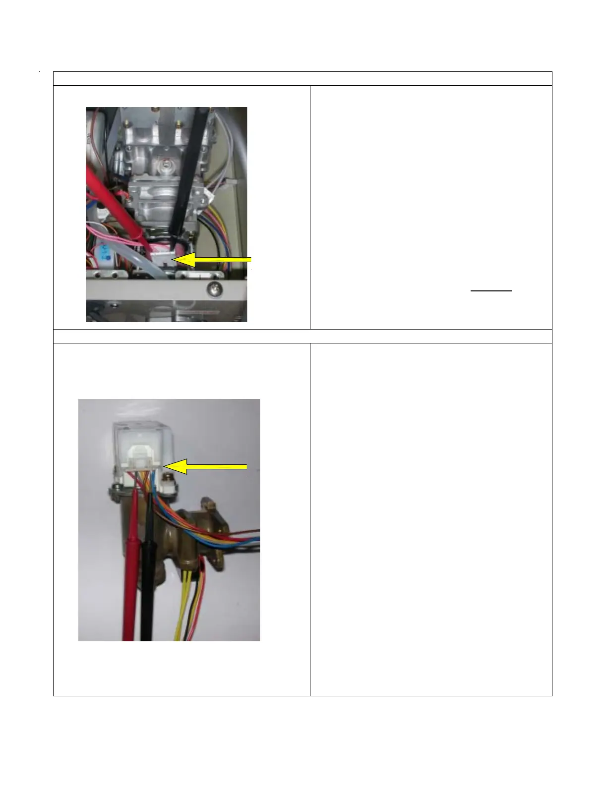
a. # Disconnect the modulating valve festoon C
2
terminals and measure the resistance at the
terminals.
Normal: 67 ~ 81 Ω
If normal, check b.
Faulty: Replace modulating valve.
b. Re-connect terminal C
2
and measure voltage
across the pink ~ pink wires when the unit is
firing.
Normal: 2 ~ 15 VDC
If normal, check c below.
Faulty: Replace the PCB unit.
c. Investigate the change in the manifold gas
pressure, when the remote control pre-set
temperature is altered from 96 ~ 140 ºF.
Normal: If the manifold pressure changes,
proceed to check item 4 below. DO NOT
adjust manifold pressures.
Faulty: Replace modulating valve.
4) Is the water flow servo normal ?
a. # Disconnect connector B
2
and measure the
resistance of the water flow servo, red ~ blue
wires.
Normal: 19 ~ 24Ω
If normal, proceed to b.
Faulty: Replace the water flow servo and sensor.
b. Disconnect connector B
2
, and measure the
voltage on the PCB unit side, were the orange
(+), and/or grey or black (-) wires connect to the
board.
Normal: 3.3 ~ 4.5 VDC
If normal, proceed to c.
Faulty: Replace the PCB unit.
c. With connector B
2
, connected (do not turn water
ON … wait for the water flow servo to return to
fully open), measure the voltage at the brown ~
grey wires.
Normal: 4 ~ 6 VDC vent limiter OFF
Faulty: Replace the water flow servo and
sensor.
d. With connector B
2
, connected (do not turn
water ON… wait for the water flow servo to
return to fully open), measure the voltage at the
yellow ~ grey wires.
Normal: Less than 0.5 VDC when unit is set at
120 °F and there is no water flowing through the
unit. .
Faulty: Replace water flow servo and sensor.

 Loading...