Rinnai Water Heater Service Manual 19 100000098 Rev B
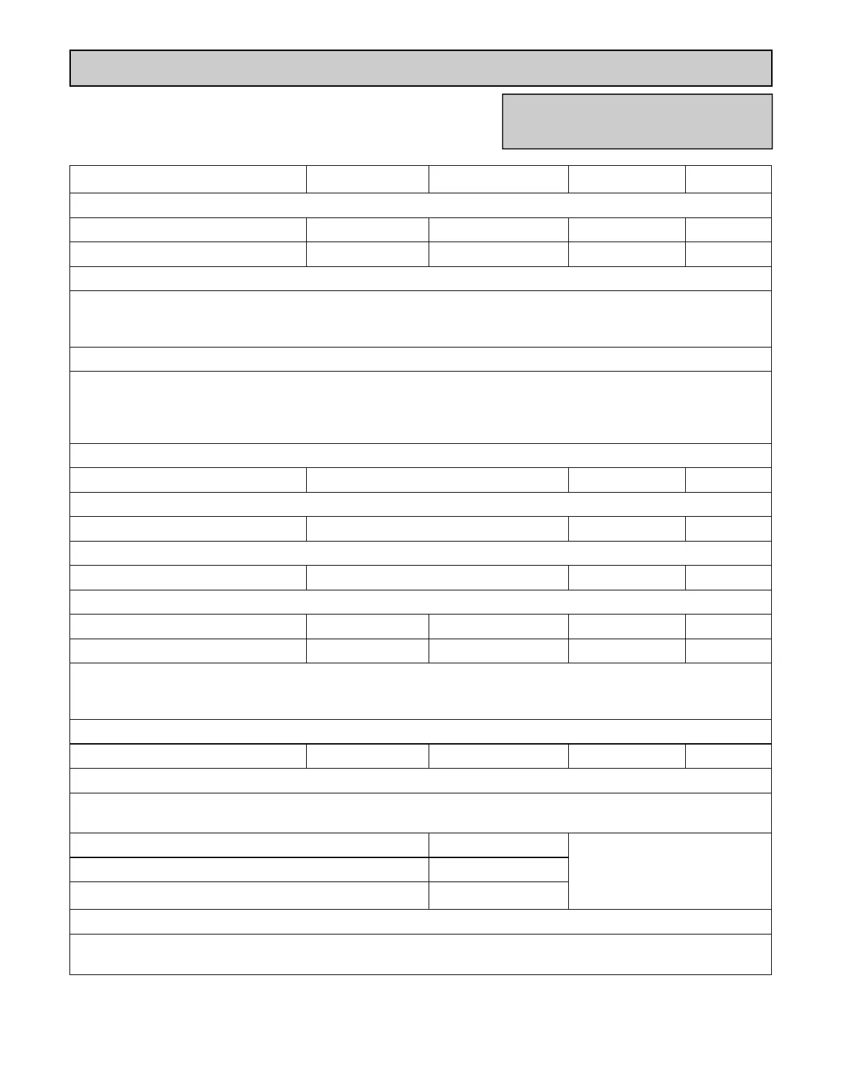
Electrical Diagnostic Points
Wire Color Voltage Resistance Connector No. Pin No.’s
Thermal Fuse / Overheat Switch
Red - Red (thermal fuse side) below 1 ohm F6 H1 1 ~ 1
Flame Rod
Place one lead of the meter to the flame rod and the other to ground. With the unit running, 5-150 VAC should be
read. Set the meter to the μ amp scale and series the meter in line with the flame rod. Proper flame circuit
should read 1 μ amp or greater. If not, then remove the flame rod and check for carbon and damage.
Thermistors
Check all thermistors by inserting meter leads into each end of the thermistor plug. Set the meter to the 20 K ohm
scale and read resistance. Applying heat to the thermistor bulb should decrease the resistance. Applying ice to
the thermistor bulb should increase the resistance. Typical resistance values are: 11.4-14 K ohm for 59°F; 6.4-
7.8 K ohm for 86°F; 3.6-4.5 K ohm for 113°F; 2.2-2.7 K ohm for 140°F; 0.6-0.8 K ohm for 221°F
Outgoing Water Thermistor
White - White see above F5 (1, 1) 3 ~ 4 (F)
Heat Exchanger Temperature Thermistor
Pink - White see above F4 (1, 1) 3 ~ 11 (F)
Orange - White see above F3 (1, 1) 3 ~ 12 (F)
Surge Protector
Black - White 108 - 132 VAC N/A D2 1 ~ 3
Blue - Brown 108 - 132 VAC N/A D1 1 ~ 3
With the power off, check the continuity through the surge protector. Check by placing one meter lead on the top
pin #1 and bottom pin #3. Check by placing one meter lead on the top pin #3 and bottom pin #1. If there is
continuity across both sets of points, then the surge protector is good.
Controller
Terminals B1 10 - 13 VDC 1.5 - 3.0 K ohms B 1 ~ 3
Frost Protection
There are electrical heating elements mounted at different points to protect the water heater from freezing.
heaters located on the hot water outlet line 180 - 207 ohms
heater located on heat exchanger piping 156 - 180 ohms
heater located on water flow sensor 24 - 28 ohms
Amp fuses
There are two inline 3 amp glass fuses. Remove the fuse and check continuity through it. If there is continuity
then the fuse is good.
Intake Air Thermistor (only on R50LSi, R75LSi, R94LSi)
Red - Red (PCB side) 11 - 13 VDC F6 H1 1 ~ 1
R50LSi, R63LSe2, R75LSe-VA,
R75LSi-VA, R94LSe-VA, R94LSi-VA