Rinnai Water Heater Service Manual 20 100000098 Rev B
Heat Exchanger and Outgoing Water Temperature
Thermistors:
Check all thermistors by inserting meter leads into
each end of the thermistor plug. Set your meter to the
20 K scale and read resistance. Applying heat to the
thermistor bulb should decrease the resistance.
Applying ice to the thermistor bulb should increase the
resistance.
Frost Protection:
This unit has frost protection heaters mounted at
different points to protect the water heater from
freezing.
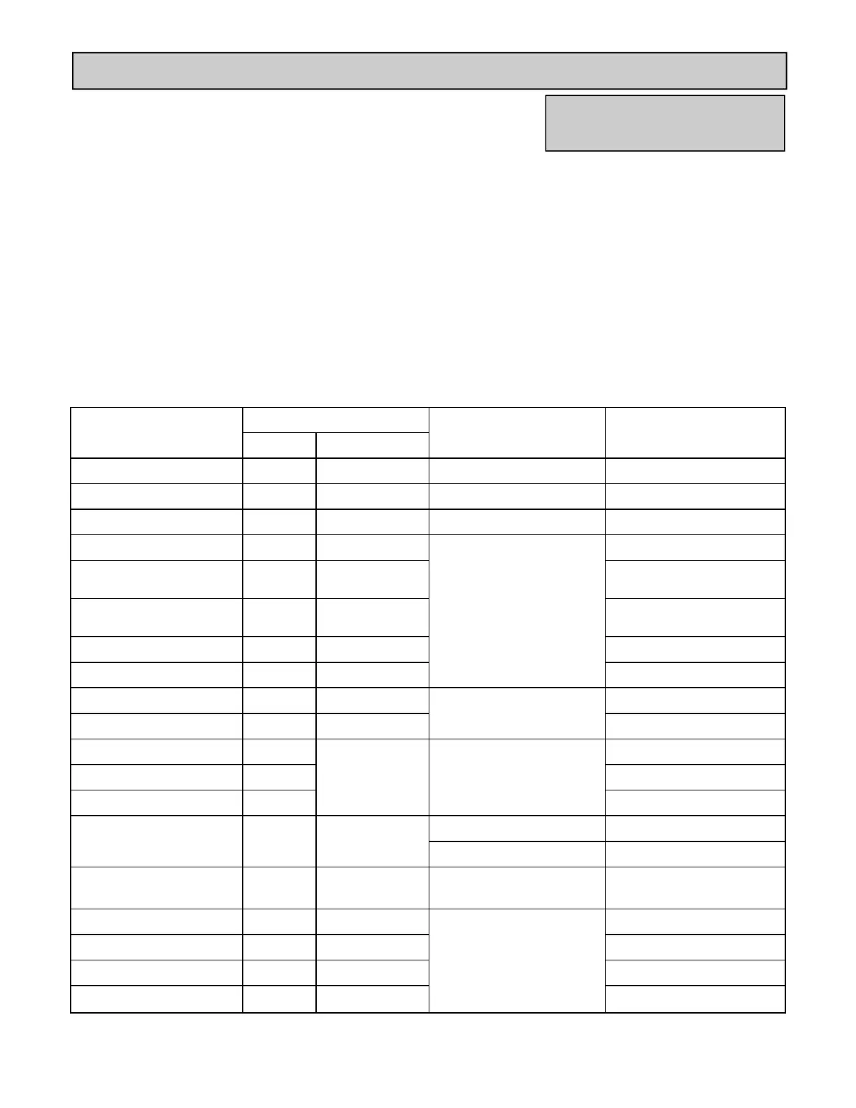
Electrical Diagnostic Points
COMPONENT MEASUREMENT POINT RANGE OF VALUE REMARKS
CN WIRE COLOR
TEMP CONTROLLER A1 Bk-Bk DC11-13V
THERMAL FUSE B1/E1 W-W BELOW 1 Ω
MOD. SOLENOID VALVE B2 O-O DC2-15V / 67-82 Ω
MAIN SOLENOID VALVE B3 P-Bk
DC11-13V / 37-43 Ω
SOLENOID VALVE 1 B4 B-Bk
(Y-Bk on V53i)
SOLENOID VALVE 2 B5 Y-Bk
(Bl-Bk on V53i)
SOLENOID VALVE 3 B6 R-Bk
SOLENOID VALVE 4 B7 O-Bk NOT ON V53i, RV53i
FLAME ROD 1 B8 Y-FR OVER 1 µ A
(DURING OPERATION)
FLAME ROD 2 M1 R-FR NOT ON V53i, RV53i
SURGE PROTECTOR C1
W-Bk AC108-132V
SURGE PROTECTOR C2
MAIN POWER CORD C3
ANTI FROST HEATER C4 W-W
88-120 Ω W (OUTDOOR) MODELS
156-211 Ω FFU (INDOOR) MODELS
IGNITOR D1 Gy-Gy
AC108-132V
(DURING IGNITION)
HEAT EXCHANGER TH E2 W-W
15ºC/59ºF: 11.4-14.0 kΩ
30ºC/86ºF: 6.4-7.8 kΩ
45ºC/113ºF: 3.6-4.5 kΩ
60ºC/140ºF: 2.2-2.7 kΩ
105ºC/221ºF: 0.6-0.8 kΩ
OUTGOING WATER TH1 E3 W-W
OUTGOING WATER TH2 E4 W-W
AIR TEMPERATURE TH E5 W-W FFU (INDOOR) MODELS
Amp Fuses:
Indoor models have one inline (5) amp glass fuse.
Outdoor models have one inline (3) amp glass fuse.
Remove the fuse and check continuity through it. If
you have continuity through the fuse then it is good.
Otherwise the fuse is blown and must be replaced.
Flame Rod:
Place one lead of your meter to the flame rod and the
other to ground. With the unit running you should read
between 5-150 VAC. Set your meter to the micro amp
scale. You should read 1 micro amp for proper flame
circuit. In the event of low flame circuit remove the
flame rod and check for carbon or damage.
V53i, R75LSe-VB, R75LSi-VB,
R94LSe-VB, R94LSi-VB