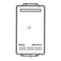
REU-2532W Series 40 Rinnai
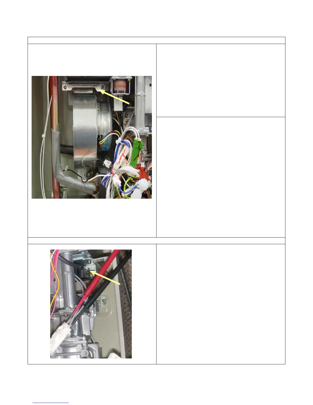
4) Is the combustion fan motor normal ?
Motor check.
If error “61” is displayed, check the combustion
fan.
a. Measure voltage at connector A
1.
Black and red
wires.
Normal: 6 ~ 45 VDC (Fan on)
0 VDC (Fan off)
If normal, check item b below.
Faulty: Replace the PCB unit.
Fan revolution sensor check.
b. Measure voltage at connector A
1,
black and
yellow wires.
Normal: 11 ~ 13 VDC or 3.1 ~ 3.7 KΩ
If normal, check item c below.
Faulty: Replace the PCB unit.
c. Measure voltage at connector A
1,
black and
white wires.
Normal: 6 ~ 45 VDC or 9 ~ 9.4 KΩ
(33 ~ 400 Hz.)
If normal, proceed to check item 5 below.
Faulty: Replace the combustion fan motor.
5) Is the sparker operating normally ?
Check the sparker module.
a. Measure voltage at connector F
8,
grey and grey
wires.
Normal: 90 ~ 110 VAC
0 VDC (when fan is off)
If normal, check b below.
Faulty: Replace the PCB unit.
b. # Disconnect connector F
8,
and measure the
resistance between the two sparker terminals.
Normal: > 1 MΩ
Faulty: Replace the igniter module.
Electrode gap should be
3
/
16
” to
1
/
4
” .
.
 Loading...