52 EX17DT and EX22DT Installation and Operation Manual
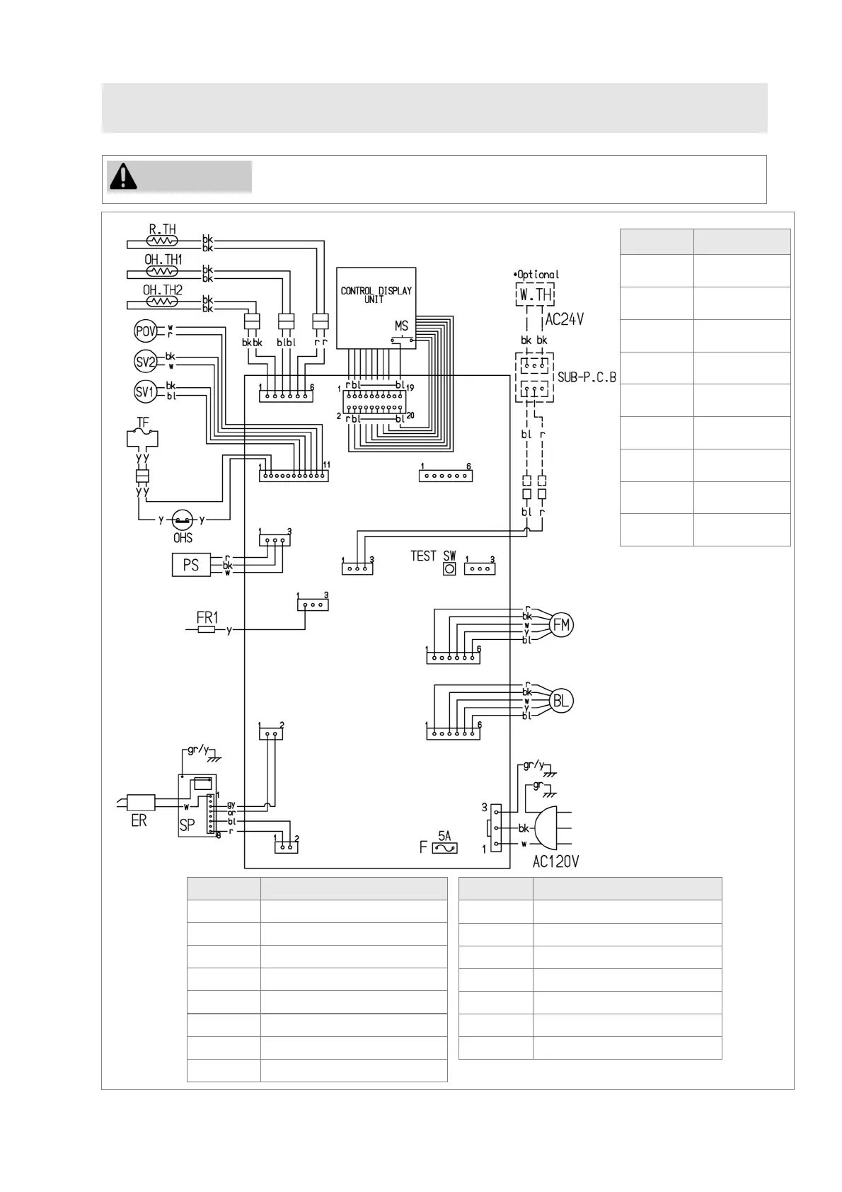
9.2 Wiring Diagram
Label all wires prior to disconnection when servicing controls. Wiring errors
can cause improper and dangerous operation.
CAUTION
Mark Parts Name
MS Main Switch
R.TH Room Thermistor
TF Thermal Fuse
F Fuse
ER Electrode
POV Modulating Solenoid Valve
W.TH Wall Thermostat
FR Flame Rod
Mark Parts Name
OH.TH1,2 Over Heat Thermistor 1,2
OHS Over Heat Switch
FM Convection Fan Motor
SP Sparker
SV1,2 Main Solenoid Valve 1,2
BL Combustion Fan Motor
PS Pressure Sensor
Figure 60: Wiring Diagram
Code Color
bk black
bl blue
gr/y green/yellow
gr green
r red
w white
y yellow
gy gray
or orange
 Loading...