PUMP
C
u
t
w
i
r
e
t
o
c
o
n
n
e
c
t
t
o
p
u
m
p
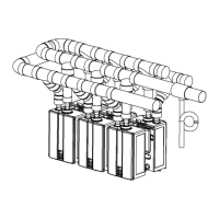
Recircula,on Mode
Pump Requirements
Pump Size
Installa,on
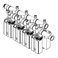
2. Install the recirculaon pump on the return line
according to the pump manufacturer installaon
instrucons. Install a check valve in the return
line as shown in the Plumbing Diagram if one is
not integrated into the pump.
3. The wire harness for the recirculaon pump is
bundled with the wire harness from the PC board.
The connector has a black and white wire with the
label “Cut wire to connect to pump”. To connect
to the pump, cut the connector, splice the wires,
and add 4 Amp fuse to the hot wire (black) of the
pump. Connect the ground wire from the pump
to a screw at the base of the water cabinet .
Refer to the Pump Electrical Connecon Diagram.
Follow Electrical Code and pump manufacturers
recommendaons.
4. Adjust the dip switch by moving the SW4 in
DIPSW 2 to ON.
For Economy mode, set SW8 in DIPSW 2 to OFF
(default).
For Comfort mode, SW8 in DIPSW 2 to ON.
5. Connect power to the water heater. Press the
Power buGon on the controller. The pump and
water heater will turn on to raise the recirculaon
loop temperature.
DIPSW 2
SW4 SW8
ON OFF
ON ON
Cut connector
and splice wires.
4 Amp
Fuse
BL
W
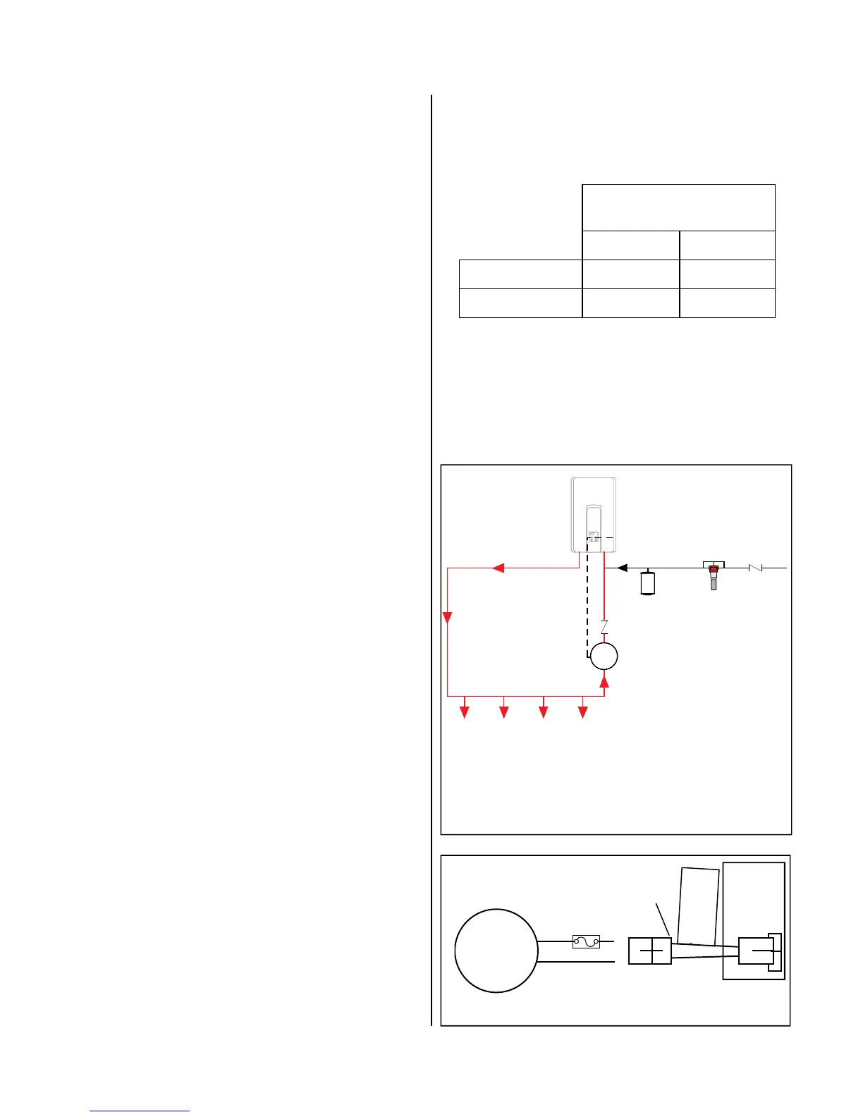
NOTE: DO NOT install scale control system within the
recirculaon loop.
HOT WATER
SUPPLY LINE
(minimum 3/4”)
COLD WATER SUPPLY LINE
PUMP
ELECTRICAL
CONNECTION
(POWER)
RECIRCULATION
LOOP
HOT WATER OUTLETS
CHECK VALVE
(REQUIRED)
CHECK
VALVE
THERMAL
EXPANSION TANK
RINNAI
SCALE
CONTROL
(RECOMMENDED)
RETURN LINE
(minimum 3/4”)
C
u
t
w
i
r
e
t
o
c
o
n
n
e
c
t
p
u
m
p
PC
Board
 Loading...