Rinstrum - R300 Series Digital Indicator Quick Start Manual Rev 1.5
Page 13
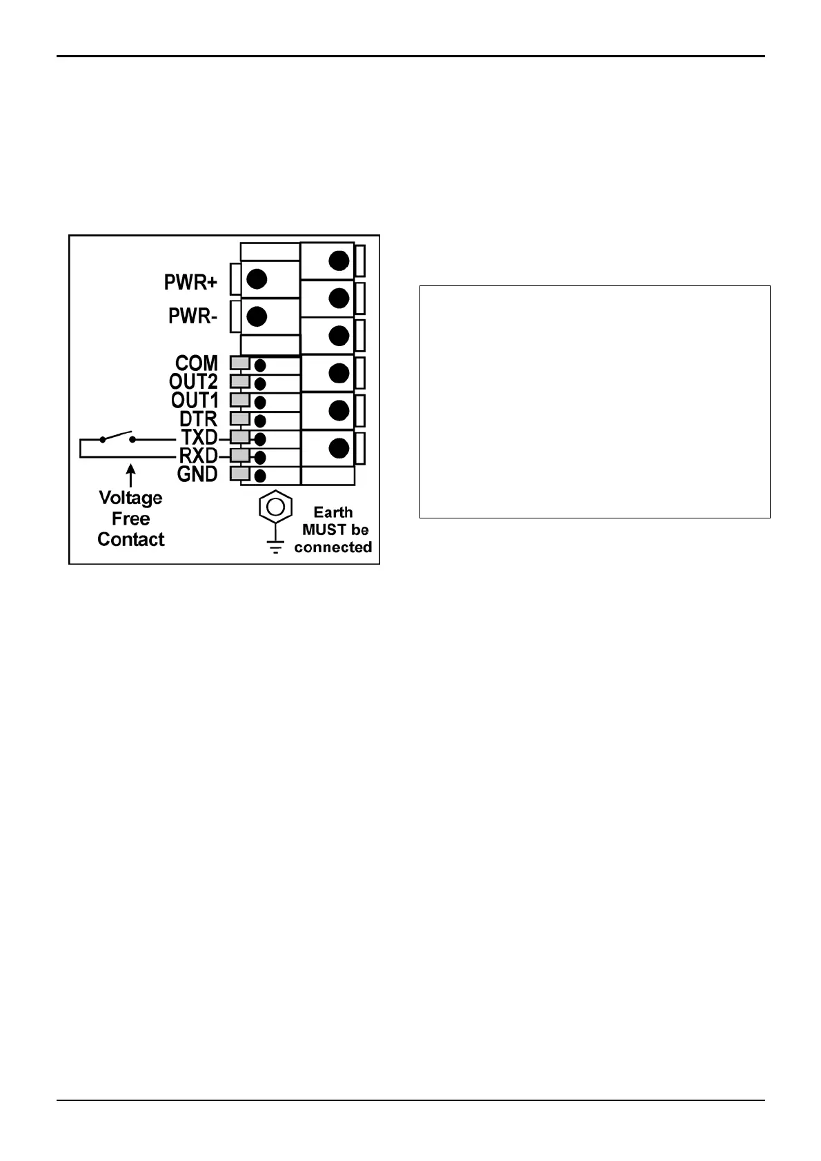
6.4.4. Remote Input
• The indicator requires a voltage free contact between TXD and
RXD to enable the remote input (ie. SPEC:REM.FN). Note:
The remote input will not function when in setup or when using
the rin-LINK.
WARNING
The remote input is a voltage
free contact (eg. button,
mechanical relay).
Connection of any active
circuitry may damage the
instrument.
6.4.5. Outputs
• Output drivers for the R320 are isolated open emitter transistor
drives that are capable of driving up to a total of 300mA.
• This configuration allows for the direct connection of the R320
outputs to most types of PLC.
• The voltage applied to the COM terminal appears on the output
lines (ie. OUT1 and OUT2) when the outputs are active (eg. to
connect to a PLC connect +24V to the common terminal). The
outputs can then be connected directly to PLC inputs so when
the outputs are active the PLC will see a 24V signal.
• To drive external loads (eg. relays), connect the relay coil
positive supply to the output common and the output line directly
to one side of the relay coil.
• Connect the other end of the relay coil to the negative supply. It
is recommended that fly-back diodes or transient suppressors be
fitted across relay coils to limit switching noise.
 Loading...