Rite‑Hite
®
Installation/Service/Owner's Manual FasTrax
®
XL
Publication: AMEN00316 2020-07-06 45
INSTALLATION
Electrical
Continued
Control Box
HIGH VOLTAGE ONLY !
T1
- PLC LOGIC -
INPUTS & OUTPUTS ON PLC
R
F2 F3
USE CLASS CC
FUSES ONLY
RATED 600V, 30A
USE CLASS CC
FUSES ONLY
RATED 600V, 30A
F5F4
F7
CR3
F1
STB
N
N
W
V
U
GND
3Ø 208-240V, 460-480V, 575V
CR1
H1 H2 H3 H4
X3 X2 X1
BRK
GND
GND
L1
L2
L3
13 A1
T1
T2
T3
14 A2
AB
MCR1
K09 10
Detect
Loop sens. Adj.
5
Pres. / pulse
678910
APEMs
Entry / Exit
Pres. / pulse
Entry / Exit
100ms / 500ms
Relay A
Relay A
Relay B
Relay B
Pulse
Not Used
1234
ON
Power
Freq. Adjust
Relay A,B
ASB
Act / Pass
Pres. Time Adj.
1 min to
8
CH2 CH1
123
45
6 7 8 9 10
6
24V
7
0V
8
CLSG
9
RE
10
BKWY
1
OPEN
2
CLS
3
STOP
4
O/C
5
COM
ACTIVATOR
POWER SAFETY
RF Com
Fault
Remote
Pairing
WIRELESS HOST
12-24VAC/DC
COM
NO
NC
ON
12
10RD433
12-24V
AC/DC
COM
NO
NC
PUL | TOG
0.5s | 10s
DELAY
NO
DELAY
POWER
HOLD
TIME
LEARN
ACT
LEARN
485
CLASS II LOW VOLTAGE ONLY !
<7822E051_NTB.pdf>
D
A
E
F
B
C
F
G
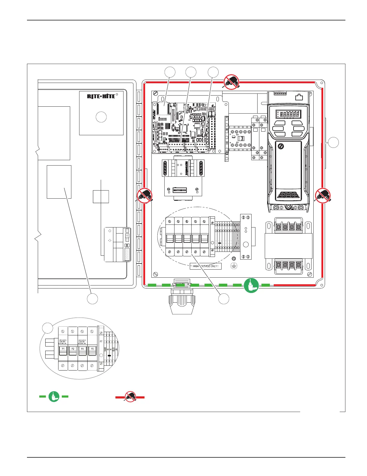
A. i-COMM 3
B. Label inside control box for i-COMM 3 Input/Output Table.
C. Incoming power terminals F1, F2, F3 for 230/460/400/575V 3Ø configuration.
D. Illuminated input LEDs.
E. Illuminated output LEDs.
F. Serial number label.
G. Incoming power terminals F1, F2 for 220V 1Ø.
= Safe area for
drilling holes.
= Un-safe area for
drilling holes.
Figure 74
 Loading...