EasyManua.ls Logo

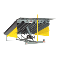
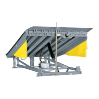
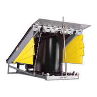
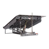
RITE-HITE LEVEL-RITE HL-800 Series User Manual

RITE-HITE LEVEL-RITE HL-800 Series
48 pages
To Next Page IconTo Next Page
Page #1 background imageLoading...
Page #1 background image
LEVEL-RITE
TM
HL-800 SERIES
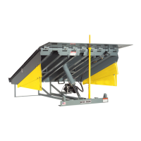
HYDRAULIC DOCK LEVELER
Owner’s Manual
PRINTED IN U.S.A. PUBLICATION NO. 1167rev.1
RITE-HITE PRINT SHOP 1-414-355-2600 NOVEMBER 2001
THIS MANUAL COVERS LEVELERS
AFTER SERIAL NUMBER M101516
By Rite-Hite

Other manuals for RITE-HITE LEVEL-RITE HL-800 Series

Questions and Answers:

RITE-HITE LEVEL-RITE HL-800 Series Specifications

General IconGeneral
BrandRITE-HITE
ModelLEVEL-RITE HL-800 Series
CategoryLifting Systems
LanguageEnglish

Summary

SAFETY WARNINGS

Lockout/Tagout Procedures

Procedures for safely de-energizing equipment during maintenance, requiring lockout devices and tags.

Electrical Safety Precautions

Ensure power source is locked out and tagged according to OSHA regulations and electrical codes.

Hazard Level Definitions

Definitions for Danger, Caution, Warning, and Important statements regarding hazards and procedures.

INTRODUCTION

Notice to User Information

Information on planned maintenance programs and contacting local representatives for support.

Pit Construction Details

Pit Dimensions by Capacity

Table detailing pit dimensions (length, width, depth) for different leveler capacities.

Pit Construction Details Continued

Anchor Layout, Materials, and Notes

Diagram for anchor layout, construction notes, and contractor's bill of materials for pit construction.

Junction Box Location

Diagram showing preferred and alternate junction box locations and dimensions for HL Series.

Installation Instructions

Typical Installation Diagram

Diagram showing a typical completed installation of the HL800 leveler within a dock wall.

Installation Safety Warnings

Warning to never be under the leveler without maintenance support and contact for unclear procedures.

Installation Instructions - Continued

General Installation Safety Precautions

Safety precautions during installation, including barricading, grounding, and lifting capacity.

Pit Positioning and Frame Details

Details on handling plates, pit side view, and positioning the leveler in the pit.

Installation Instructions - Continued

Pit Gap and Shim Placement Details

Diagrams showing gap filling, frame angle cutting, and shim placement in the pit.

Installation Instructions - Continued

Frame and Shim Installation Details

Diagrams detailing shim placement, frame recess/flush conditions, and weld points.

Installation Instructions for Self-Forming Pans

Foundation Opening and Pad Preparation

Specifications for flush and surface mount foundation openings and leveler pad preparation.

Foundation Wall Diagrams

Diagrams illustrating flush and surface mount details for foundation wall and pit openings.

Installation Instructions for Self-Forming Pans - Continued

Pit Steel and Mounting Plate Installation

Details for pit steel installation and the optional DOK-LOK mounting plate.

Installation Instructions for Self-Forming Pans - Continued

General Safety for Pan Installation

Safety warnings for installation, including barricading, grounding, and lifting.

Unit Lifting and Positioning

Procedure for lifting and positioning the leveler unit on the pad.

Installation Instructions for Self-Forming Pans - Continued

Mounting Type and Anchor Specifications

Details for flush mount, surface mount, standard anchor points, and optional DOK-LOK ITC.

Installation Instructions for Self-Forming Pans - Continued

Final Concrete Pour Procedure

Instructions for the final concrete pour, including securing the leveler and covering openings.

Concrete Pour Requirements

Key requirements for concrete: level with pan top, well vibrated, and minimum 6" thick.

Installation Instructions for Self-Forming Pans - Continued

Shipping Bands and Pit Steel Anchoring

Safety for shipping bands and details for anchoring to pit steel or using anchors.

Electrical Installation Instructions

Pre-Installation and Component Overview

Steps before installation, components of a complete electrical installation, and wiring instructions.

Electrical Component Requirements

Details on Load Center, Disconnect, Control Box, Junction Box, Power Unit, Conduit, and Wire.

Electrical Installation Instructions - Continued

Typical Electrical Installation Diagram

Diagram illustrating a typical electrical installation layout for the dock leveler.

Installation Completion

Bumper Installation Procedures

Instructions for installing molded (standard) and laminated (optional) bumpers.

Bumper Installation Details

Details on positioning, securing, and applying logos for molded and laminated bumpers.

Installation Completion - Continued

Lip Support Installation Procedure

Procedure for installing lip supports for 20" lips, including welding or anchoring.

Hydraulic Fluid Check

Hydraulic Oil Level Check Procedure

Instructions for checking the hydraulic oil level, emphasizing safety and correct oil type.

Hydraulic System Safety Warning

Warning to never go under the leveler without engaging the maintenance support.

Operating Instructions

General Operating Safety Warnings

Safety warnings to prevent personal injury during leveler operation.

Normal Leveler Operation (Without ARTD)

Steps for operating the leveler without the ARTD feature, including raising and lowering.

Platform Load Warning

Do not operate the leveler if any load is on the platform.

Operating Instructions - Continued

Below Dock Loading Operation

Procedure for operating the leveler for below dock loading, including lip extension and retraction.

Leveler Storage Procedure

Instructions on how to properly store the leveler when not in use.

Platform Load Warning

Do not operate the leveler if any load is on the platform.

Maintenance Procedures

Maintenance Safety and Precautions

Safety warnings for maintenance, including barricading work area and engaging maintenance support.

Suggested Maintenance Schedule

Recommended maintenance schedule for the leveler, covering daily, 90-day, and 360-day intervals.

Troubleshooting

Platform Not Raising (Motor Not Running)

Lists probable causes and remedies for the platform not raising due to motor issues.

Troubleshooting - Continued

Platform Not Raising (Motor Running)

Probable causes and remedies for platform not raising when the motor is running.

Troubleshooting - Continued

Continuous Operation & Slow Lip Extension

Causes and remedies for continuous running and slow/incomplete lip extension.

Troubleshooting - Continued

Lip Extended & Platform Not Lowering

Causes and remedies for the lip remaining extended and the platform failing to lower.

Troubleshooting - Continued

Slow Platform Raise & Lip Issues

Causes and remedies for slow platform raising and issues with lip extension.

Troubleshooting - Continued

Unit Will Not Recycle

Causes and remedies for the unit failing to recycle or operate through its cycles.

Adjustment Procedures

Lip Stop Bolt Adjustment

Adjusts the lip position when the leveler is stored.

ARTD & Restrictor Limit Switch Adjustments

Adjustments for ARTD cam and restrictor limit switch for proper lip positioning and rise height.

Limit Switch Diagrams

Diagrams showing the restrictor and ARTD limit switches and their adjustment mechanisms.

Adjustment Procedures - Continued

Valve Adjustment Safety & Procedure

General warnings and procedures for valve adjustments, emphasizing safety and trained technicians.

Shuttle Valve Adjustment

Procedure for adjusting the shuttle valve to control the leveler's descent speed.

Valve Diagrams

Diagrams of the power unit end head and shuttle valve nominal setting.

Electrical Schematics

115V & 208-230V 1PH Schematics

Electrical diagrams for 115V and 208-230V single-phase configurations.

Electrical Schematics - Continued

208-230V & 460V 3PH Schematics

Electrical diagrams for 208-230V and 460V three-phase configurations.

Electrical Schematics - Continued

115V & 208-230V 1PH Schematics with Options

Diagrams for single-phase with optional ARTD and OHD features.

Electrical Schematics - Continued

208-230V 3PH Schematics with Options

Diagram for three-phase 208-230V with optional ARTD, DOK-LOK, and OHD ITL.

Electrical Schematics - Continued

460V 3PH Schematics with Options

Diagram for three-phase 460V with optional ARTD, DOK-LOK, and OHD ITL.

Hydraulic Schematics

Power Unit Assembly Schematic

Diagram of the power unit assembly showing pump, motor, valves, and filters.

Frame Replacement Parts Drawing

Frame Assembly Parts Lists

Lists of replacement parts for 6' and 8' long frame assemblies with part numbers.

Platform Replacement Parts

Platform Assembly Parts Lists

Detailed parts lists for 6' and 8' long platform assemblies with item numbers and quantities.

Control Box Replacement Parts - Non-Metallic

Non-Metallic Control Box Parts List

List of non-metallic control box components with part numbers for various configurations.

Control Box Replacement Parts - Steel Gray

Steel Gray Control Box Parts List

List of steel grey control box components with part numbers for 208-230V and 460V.

Hydraulic Replacement Parts

Hydraulic Components Parts List

List of hydraulic components for 6' and 8' long levelers, including part numbers.

Optional ARTD Replacement Parts

ARTD Option Parts List

List of replacement parts specifically for the Optional ARTD system.

Weather Seal Replacement Parts

Weather Seal Parts List

List of parts for weather seals, including channels, inserts, and screws for different leveler sizes.

Warranty Information

Standard Warranty Policy Details

Details the standard warranty policy, coverage, and exclusions for Level-Rite™ Dock Levelers.

Warranty Conditions and Voiding Factors

Outlines conditions for warranty claims and factors that void the limited warranty.

Related product manuals