EasyManua.ls Logo

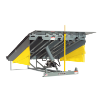
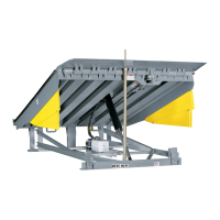
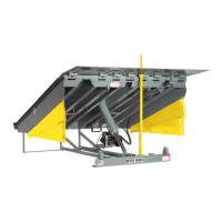
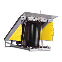
RITE-HITE RHV Series User Manual

RITE-HITE RHV Series
34 pages
To Next Page IconTo Next Page
Page #1 background imageLoading...
Page #1 background image
RHV
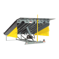
Dock Leveler
Owners Manual
This Manual Covers Dock Levelers Built After Serial Numbers:
07AD930001M and up
PRINTED IN U.S.A.
RITE-HITE PRINT SHOP
PUBLICATION NO. 1218
FEBRUARY 2008
MADE IN U.S.A.
part of the SMOOTH TRANSITION DOK SYSTEM
TM

Questions and Answers:

RITE-HITE RHV Series Specifications

General IconGeneral
TypeVertical Reciprocating Conveyor (VRC)
Platform SizeCustom sizes available
Power SourceElectric
ControlsPush-button
Safety Featuresinterlocks, emergency stop

Summary

RHV Dock Leveler Manual Introduction

Safety Warnings and Procedures

Lockout/Tagout Procedures

Details OSHA requirements for locking out power sources during maintenance and repairs.

Operational Safety Hazards

Danger: Crush Hazard Warning

Highest safety alert; failure to follow instructions may result in severe injury or death.

Warning: Operational Hazards

Statement of serious hazard; failure to follow instructions could cause injury or death.

Additional Safety Precautions

Caution: Safe Operating Procedures

Safe operating procedures; ignoring them may cause personal injury.

Important: Machine Damage Prevention

Procedures to follow to prevent machine damage.

Maintenance Safety Protocols

Danger: Platform Path Safety

Highest safety alert; failure to follow instructions may result in severe injury or death.

Warning: Maintenance Area Safety

Advises posting warnings and barricading the area during maintenance.

Maintenance Pin Engagement Procedure

Illustrates the engagement and disengagement procedures for the maintenance pin.

Owner Responsibilities

Operating Instructions Overview

Danger: Operating Path Safety

Highest safety alert; failure to follow instructions may result in severe injury or death.

Warning: Lip Handling Safety

Statement of serious hazard; failure to follow instructions could cause injury or death.

Caution: Trained Personnel Operation

Equipment should only be operated by trained personnel.

Important: Leveler Operation Notes

Notes regarding leveler operation and maintenance pin engagement.

Lowering the Leveler Platform

Step-by-step instructions on how to lower the dock leveler platform.

Raising the Leveler Platform

Step-by-step instructions on how to raise the dock leveler platform.

Dock Leveler Operation Details

Lowering Leveler to Working Position

Illustrates the process of lowering the dock leveler to its working position.

Raising Leveler to Vertical Position

Illustrates the process of raising the dock leveler to its vertical stored position.

End Load Operations

End Load Operating Procedure

Detailed steps for operating the dock leveler for end load applications.

Figure 5: End Load Illustration

Illustrates the steps involved in handling end loads with the dock leveler.

Below Dock End Load Operations

Figure 6: Below Dock End Load

Illustrates the procedure for below dock end loads from a horizontal position.

Figure 7: Below Dock End Load

Illustrates an alternative view or step for below dock end loads.

Horizontal Position Operations

Figure 8: Raise Leveler and Extend Lip

Illustrates raising the leveler and extending the lip from a horizontal position.

Figure 9: Lowering Leveler to Working Position

Illustrates lowering the leveler to the working position with the lip on the truck floor.

Maintenance Procedures and Schedules

Danger: Maintenance Path Safety

Highest safety alert; failure to follow instructions may result in severe injury or death.

Caution: Servicing Equipment

Equipment should only be operated or serviced by trained personnel.

Suggested Leveler Maintenance

Outlines suggested maintenance procedures for the dock leveler.

Daily Maintenance Tasks

Daily tasks to be performed for routine maintenance of the dock leveler.

90-Day Maintenance Tasks

Maintenance tasks to be performed every 90 days.

180-Day Maintenance Tasks

Maintenance tasks to be performed every 180 days.

Advanced Maintenance and Lubrication

360-Day Maintenance Tasks

Maintenance tasks to be performed annually (360 days).

Figure 10: Lubrication Points

Illustrates the lubrication points on the dock leveler.

Hydraulic Adjustments and Valve Settings

Important: Valve Adjustment Warning

Procedures to follow to prevent machine damage during valve adjustment.

Caution: Trained Personnel for Adjustments

Equipment should only be operated or serviced by trained personnel.

Counterbalance Valve Adjustment

Instructions for adjusting the counterbalance valve for proper operation.

Figure 12: Counterbalance Valve Diagram

Diagram showing the counterbalance valve component.

Figure 13: Leveler at Dock Height

Illustrates the leveler's position at dock height for adjustment purposes.

Tilt Back Adjustment Procedure

Danger: Tilt Back Operation Safety

Highest safety alert; failure to follow instructions may result in severe injury or death.

Important: Level or Plumb Line Usage

Guidance on using level or plumb lines for tilt back adjustment.

Leveler Tilt Back Adjustment Steps

Detailed steps for adjusting the tilt back mechanism of the leveler.

Figure 14: Tilt Back Adjustment Illustration

Illustrates the tilt back adjustment process and measurement.

Troubleshooting Common Issues

Unit Will Not Operate

Addresses issues where the dock leveler unit fails to operate.

Unit Functions Slowly

Addresses issues where the dock leveler operates at a reduced speed.

Troubleshooting Advanced Issues

Platform Falls Too Slowly

Troubleshooting steps for when the platform descends too slowly.

Platform Falls Too Quickly

Troubleshooting steps for when the platform descends too rapidly or has too much float.

Platform Drops Suddenly

Addresses issues where the platform drops suddenly and then stops functioning.

Hydraulic System Schematic

Figure 15: Hydraulic Schematic Diagram

A detailed diagram illustrating the hydraulic system components and flow.

Electrical Schematics (120V)

Figure 16: 120V 1 Phase Schematic

Electrical schematic for a 120V, 1-phase power supply.

Electrical Schematics (240V Single Phase)

Figure 17: 240V 1 Phase Schematic

Electrical schematic for a 240V, 1-phase power supply.

Electrical Schematics (240V Three Phase)

Figure 18: 240V 3 Phase Schematic

Electrical schematic for a 240V, 3-phase power supply.

Electrical Schematics (380V Three Phase)

Figure 19: 380V 3 Phase Schematic

Electrical schematic for a 380V, 3-phase power supply.

Electrical Schematics (480V Three Phase)

Figure 20: 480V 3 Phase Schematic

Electrical schematic for a 480V, 3-phase power supply.

Electrical Schematics (575V Three Phase)

Figure 21: 575V 3 Phase Schematic

Electrical schematic for a 575V, 3-phase power supply.

Replacement Parts: Lip and Platform Components

Replacement Parts List: Lip and Platform

Replacement Parts: Hydraulic Components

Replacement Parts List: Hydraulic Components

Replacement Parts: Hydraulic Manifold

Replacement Parts: Shim Kit

Replacement Parts: Control Box Components

Replacement Parts List: Control Box

Standard Warranty and Liability

Limitation of Liability

Limits RITE-HITE's liability for loss of use or consequential damages.

Related product manuals