EN
30 Rittal PDU metered/metered plus/switched/managed
6.2 Settings via the PDU website
Using a network cable, connect the device to your computer via the Ethernet interface (fig. 12,
item 9).
Change your computer's IP address to any address within the range 192.168.0.xxx, e.g.
192.168.0.191. The default address 192.168.0.200 of the device must not be used.
Set the subnet mask to the value 255.255.255.0.
If applicable, switch off the proxy server in the browser to facilitate a direct connection to the device.
In the browser, enter the address http://192.168.0.200 (fig. 13, item 1). The login dialog for logging
in to the device will be displayed.
Log in with the username admin and the password admin (fig. 13, item 2).
In the left-hand section of the overview window (navigation area), click the Processing Unit entry
(fig. 13, item 3), and in the right-hand section (configuration area), click the Configuration tab
(fig. 13, item 4).
In the Network group box, click on the TCP/IP button (fig. 13, item 5).
In the TCP/IP Configuration window, change the device's IP address in the IPv4 Configuration
group box to an address permitted in the network (fig. 13, item 6).
If necessary, correct the settings for the subnet mask and the gateway.
Alternatively, select the "DHCPv4" setting instead of "Manual" for automatic IP allocation.
Click on the Save button to change your settings.
Change the network settings of your computer to its original values for the IP address and the subnet
mask.
Disconnect the network cable from your computer.
Connect the PDU to your Ethernet LAN with a network cable.
For any required software updates, please visit www.rittal.com or contact Rittal Service (see section 9).
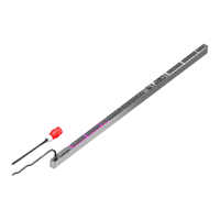
6.3 Connection of sensors
A maximum of eight sensors and handle systems from the CMC/PDU portfolio can be connected to
the intelligent PDUs, e.g. temperature, humidity, access, smoke, leakage, air flow.
Radio sensors are not supported.
Connect one of the sensors from the accessories range to the CAN bus interface of the PDU using
a CAN bus connection cable (fig. 12, item 12).
After connecting a sensor, the sensor software will be updated first of all, if necessary. The status
LED of the sensor remains continuously blue and also flashes purple during the entire update pro-
cess. In addition, the status LED of the PDU flashes white, and a corresponding message appears
on the website.
Status change display following completion of an essential update:
– The two green and the two red CAN bus LEDs on the CAN bus connection of the connected sen-
sor will start to flash.
– The multi-LED of the PDU flashes continually in the sequence green – orange – red.
Note:
You may need to use a cross-over cable for this purpose.
Note:
The following sections describe in detail how to make the setting for the IPv4 protocol.
Further notes regarding the TCP/IP configuration can be found in section 1.1.
Settings of the PDU
 Loading...