BLOCKSYSTEM FA - FT Pag. 23 REV. 04 10/07
UK
7. 6
Machine status display
Press and release SET: the display will read “SEt” or “AAL” if there are any alarms in progress
Press UP or DOWN until the required status is displayed
AAL alarms in progress (if present)
SEt setpoint
Pb1 coldroom temperature probe value
Pb2 evaporator temperature probe value
Pb3 probe 3 value (if present)
Out relay outputs status
InP digital inputs status
Press SET to view the value
For alarm status, output status or input status, press UP or DOWN to scroll through the alarms in
progress, the outputs or the inputs,
Press SET or ON/OFF (or wait for the 5-second timeout) to return to the status list
Press ON/OFF (or wait for the 5-second timeout) to return to the normal display mode
.
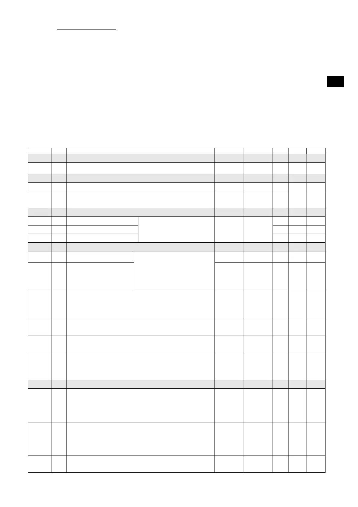
Code Level Descr. Range Unit MBP LBP HBP
List of -PPS passwords
PPA
Parameters access password
Entering a pre-set password will give access to protected parameters
0 … 255 - - -
List of -rEG adjustment parameters
SEt
0 Setpoint LSE …HSE °C [°F] 2 -18 5
diF
1 Differential
temperature > setpoint + diff. -> adjustment On
temperature ≤ setpoint -> adjustment Off
0.1 … 50.0 °C [°F] 2 2 2
List of -Pro probe parameters
CA1
1 Probe 1 calibration 0 0 0
CA2
1 Probe 2 calibration 0 0 0
CA3
1 Probe 3 calibration
The value assigned to this parameter
is added to (positive value) or taken
away from (negative value) the
temperature detected by the probe
-20.0 …
20.0
°C [°F]
0 0 0
List of -CPr compressor parameters
Ont
1 Compressor ON time in the
event of probe failure
0 … 60 min 15 15 15
OFt
1 Compressor OFF time in the
event of probe failure
In the event of an adjustment probe
error, the compressor is enabled in
cyclical mode with set operation and
off times. In particular:
Ont=0: the compressor remains off
Ont>0 and OFt=0: the compressor
remains on
0 … 60 min 15 15 15
dOn
1 Compressor activation delay
The time, starting from the switch on request, after which the compressor
is effectively activated.
In the event of network control in sequential mode, this represents the
activation delay from compressor to compressor
0 … 250 sec 0 0 0
dOF
1 Minimum compressor OFF time
The time, starting from the moment of deactivation, for which it is not
possible to restart the compressor
0 … 60 min 3 3 3
dbi
1 Delay between switch on times
The time, starting from the moment of previous activation, for which the
compressor cannot be restarted.
0 … 60 min 0 0 0
OdO
1 Outputs delay at power-on (compressor, fans, defrosting)
This is used to delay the enabling of adjustments after the instrument has
been switched on for a set amount of time.
The transition from stand-by to machine activated (ON command from
the keyboard) bypasses this delay
0 … 60 min 3 3 3
List of -dEF defrosting parameters
dtY
1 Defrosting type
0 = heating element: ends at temperature or after maximum safe time
(timeout)
1 = hot gas: ends at temperature or after maximum safe time (timeout)
For defrosting using a heating element, there is a 1 second delay between
the compressor switching off and the defrosting relay being triggered
0,1 1 1 0
dit
1 Defrosting interval
The maximum time (from start to start) between two consecutive
defrosting cycles. When this time expires, a defrosting cycle is enabled
(cyclical defrosting). The timer is reset at each defrosting request (even if
not cyclical).
0 = cyclical defrosting disabled
0 … 250 h 4 4 4
dct
1 Defrosting interval count mode
0 = counts if the compressor is operating
1 = counts all the time
0,1 1 1 1
 Loading...