BLOCKSYSTEM FA - FT Pag. 27 REV. 04 10/07
UK
Code
displayed
Description Notes
OFF unit in stand-by (operation disabled) remains until the next ON command
dF defrosting in progress see par. “ddL”
dFu defrosting not performed displayed for 2 seconds when the defrosting
command is not performed because the evaporator
temperature is already above the defrosting end
temperature (parameter dst)
uM master unit
uSx slave x unit
at switch on, the network configuration of the unit is
displayed
Cn terminal/control connection interrupted the terminal is not receiving data from the control
If the terminal/control connection does not operate correctly at switch on, the terminal display will read
“88,8” and the LEDs will all be switched off.
9.
EMERGENCY SYSTEM
PLEASE NOTE: A specialist technical engineer must only perform the operations described here
below.
If the electronic control unit breaks down or presents operating anomalies and it is impossible to
replace it immediately, there is an EMERGENCY SYSTEM that can be used to maintain the unit in
operation until it can be replaced.
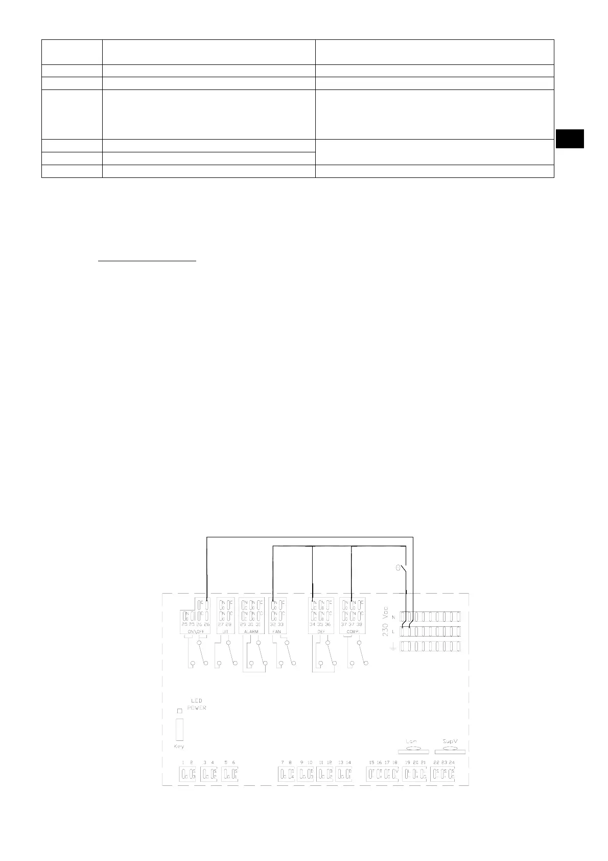
To use this system, proceed as follows:
1. Cut off power to the Blocksystem
2. Remove all jumpers between the L terminals and the common contacts of the card relays
(terminals 25-28-33-36-38)
3. As shown in the diagram, connect a thermostat between the L terminal, the NO terminals
(terminals 32,37) and the NC terminal (terminal 34) of the compressor, defrosting and fan
relays (COMP, DEF and FAN)
4. Fit a jumper between the L terminal and the NO terminal of the ON/OFF relay (terminal 26
supplying power to the crankcase heaters, door and waste, where fitted).
5. Connect the Blocksystem back to the mains power, setting the thermostat to the required
temperature.
6. PLEASE NOTE: This connection can only be used momentarily. Contact your dealer as soon as
possible to replace the malfunctioning card.
7. PLEASE NOTE: Defrosting will be cut out for the entire emergency phase and for this reason, we
recommend that cold room door opening be kept to a minimum.
8. When fitting the new control unit, restore all of the connections described in points 2,3,4 and 5.
Key:
T = Thermostat
T