ST-SP Pag. 46 Rev 02 05/13
UK
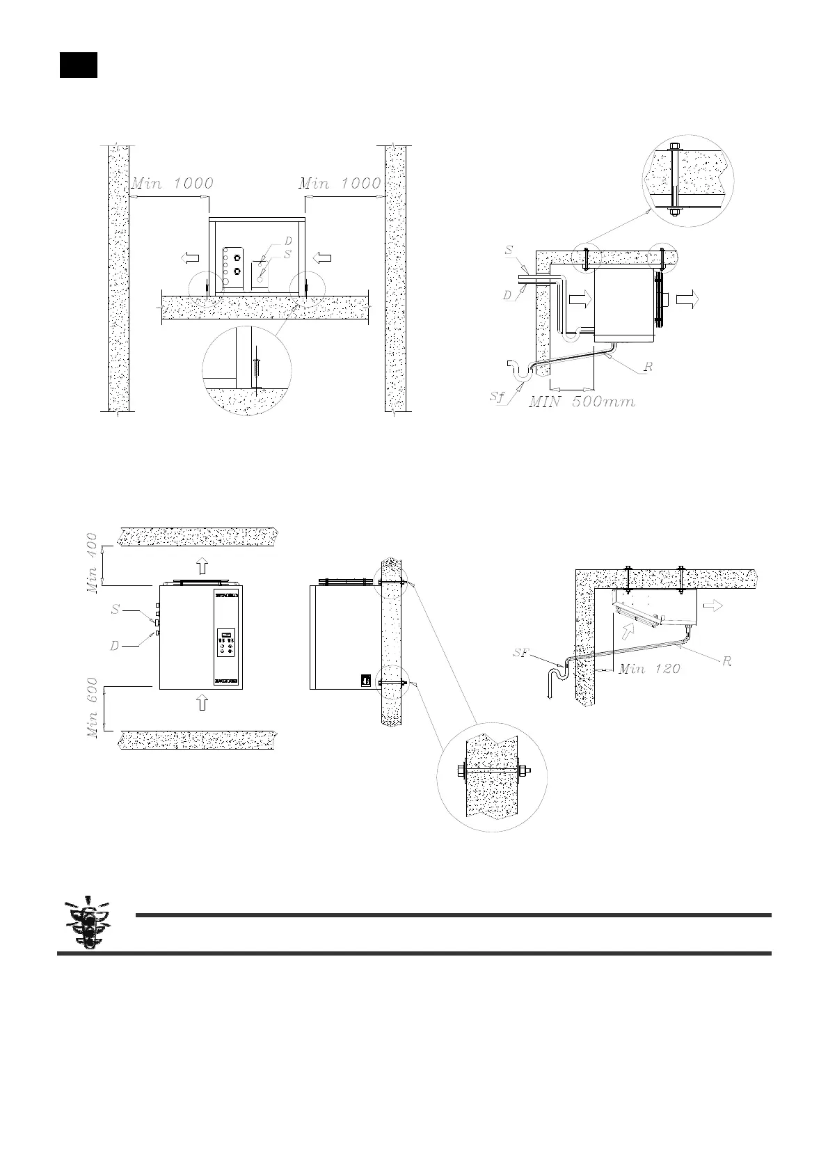
Picture 3 installation ST machine
Picture 4 installation SP machine
on
off
set
7. Make another hole for the micro-port cable, the temperature probes and defrost end. N.B. it is necessary that these
cables are placed away from the ones which carry the electrical power to avoid signal interference.
ATTENTION: the SPM300 / SPM370 / SPL350 / SPL450 models are supplied with two support legs. For the
mounting position, see the corresponding technical sheet shown in Paragraph 9 - Attachments.
Installation of the Evaporator
See Picture 3 and Picture 4 and the specifications listed in Chapter 9 - Attachments.
Refrigerator Connection
To carry out this connection provide the liquid and aspiration pipe, according to the diameters of the connections present on the
machine.
The recommended diameters correspond to the maximum lengths of 10 meters. For greater lengths the diameters must be resized
to ensure the correct gas speed.
The pipes must be fixed to the wall at all corners, welds, or every 1.5-2 meters along straight sections.
Legenda
S = Tubo di aspirazione
D = Tubo di mandata
Sf = Sifone scarico acqua
R = Resistenza di scarico (solo per modelli MBP e LBP)
Key
S = Suction pipe
D = Discarge pipe
Sf = Water drainage siphon
R = Drainage heater (MBP and LBP models only)